41 allen-bradley 700 relay wiring diagram
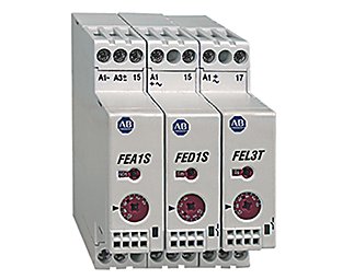
700-N Low Profile Industrial Relays | Allen-Bradley United ... 700-N Low Profile Industrial Relays | Allen-Bradley United States NEMA Low Profile Industrial Relays Our Bulletin 700-N Industrial Relays are a low profile, high reliability switching solution. These electrically held relays have manual override capability with easy-to-identify status indication on the highly visible red bar. Allen Bradley 700 Series Relay Contact Conversion. - YouTube Converting Allen Bradley 700 Series Relay Contacts. Simple, fast conversion of the 700 Series Control Relay contacts from either NO (normaly open) to NC (nor...
How To Read A Relay Wiring Diagram - U Wiring The square relay pinout shows how the relay socket is configured for wiring. The same evolution in protective relay logic also increased the importance of having a method of detecting the basic overall logic on one diagram. 29 Allen Bradley 700 Relay Wiring Diagram Example Database. A relay has four basic terminals 85 86 30 and 87.
Allen-bradley 700 relay wiring diagram
Allen Bradley 700 Relay Wiring Diagram - Wiring Diagram 700 N Low Profile Relays Allen Bradley Denmark 700 Ha33z2 3 4 Ha General Purpose Base Relay 10 Amp Contact 3pdt 220v Dc Push To Test Manual Override Function And Pilot Light Quad Industry Gmbh Allen Bradley 700 Hc22z24 4 Hc General Purpose Square W Blade Terminal Relay Dpdt 10a Contact Low Energy Rating 10v 10ma 24v Dc Pilot Light State Electric PDF Bulletin 700-HR Plug-in Timing Relays - Harvard University For use with all Bulletin 700- HRs and -HX timing relays. 1700-HN132 Cat. No. 700-HN132 Pre-Printed Identification Tags —contains 10 sheets of pre-printed and blank tags. Each sheet contains 13 sets of the markings CR…9CR, TR…9TR, M…9M, F, R, 1S, and 117 blank tags. Tags are peel-off with sticky backing for easy placement on relays. 10 700-N40 allen bradley 700 hk36al k wiring diagram - Wiring Diagram ... allen bradley 700 hk36al k wiring diagram Wiring Diagram Line Wiring Diagram. Wiring Diagram Line We are make source the schematics, wiring diagrams and technical photos ... Bulletin 700 hps pcb pin style safety control relay pp031a en p dial timing relays allen bradley united states layout 1 page hf hx multifunction digital timer user manual ...
Allen-bradley 700 relay wiring diagram. Allen Bradley 700 Relay Wiring Diagram - GORGEOUS DIAGRAM 700 N Low Profile Relays Allen Bradley United States. Wiring Diagrams ww introduction This booklet has been prepared as a guide to some of the useful ways Allen-Bradleys manual and magnetic across-the-line starters may be applied. 44 Beautiful 24vdc Relay Wiring Diagram Relay Electronic Parts Electromagnet Allen-Bradley-700-HRC12TU24.pdf Preferred availability cat. nos. are bold. ... 8-Pin for use with Bulletin 700-HR and -HX timing relays. ... PNP Wiring Diagram.9 pages Download Allen Bradley 700 Relay Wiring Diagram Pictures ... Home » wiring diagram » allen bradley safety relay wiring diagram. 2004 polaris sportsman 600 twin wiring diagram. Allen bradley 700 series relay contact conversion. First choose the wire then the reel number where you want it spooled. 2004 polaris sportsman 600 twin wiring diagram. Source: General purpose relays timing relays u0026 timers ... Bulletin 700-HPS PCB Pin Style Safety Control Relay 700 ... Wiring Diagrams Coil Voltage Package Quantity Cat. No. U.S./Canada International DPDT 2-Pole 2 Form C AgNi + Au Gold Plated Mechanically Linked Contacts 8 A 6V DC 10 700-HPSXZ06 12V DC 10 700-HPSXZ12 24V DC 10 700-HPSXZ24 48V DC 10 700-HPSXZ48 60V DC 10 700-HPSXZ60 110V DC 10 700-HPSXZ1 125V DC 10 700-HPSXZ01 DPDT 2-Pole
Overamping what to do - fendn.de Overamping what to do. [email protected] "Characters as adored as Sam & Max are easy to mess up—making it all the more impressive that in both technical and creative aspects, Telltale got Sam & Max right, and the result is a delightful series of short games that could potentially have Jan 25, 2022 · Overamping is the term we use to describe what one might consider an “overdose” on … Relay and Timer Specifications Technical Data - Literature ... 4 Mar 2022 — Wiring Diagrams. Coil Voltage. Cat. No.(1). (1) LED Option: Add suffix (-4) to the selected 700-HA Relay Cat. No., except for the 240V AC ... Allen Bradley Safety Relay Wiring Diagram - Wirings Diagram There are two things which are going to be present in any Allen Bradley Safety Relay Wiring Diagram. The first element is symbol that indicate electrical element in the circuit. A circuit is generally composed by various components. Another thing that you will come across a circuit diagram would be lines. Obsolete & Rare Parts Catalog - Page 2 - PE Energy ... Item Manufacturer Description 2.25065 O-rings 21 INPUT SHAFT 36 Bit breaker for 36″ bit (Tricone) For use of in Rotary Table 49 1/2″ w/ MPCH master bushing 37 1/2″ 37 Bit breaker for 28″ bit (Tricone) For use in Rotary table 49 1/2″ w/ MPCH master bushing 37 …
General Purpose Relays 1 See Bulletin 700-HA Relay, Socket, and Retainer Clip Reference Chart below. ‡ For pre-printed marker cards, turn to the following 1492 sections (tab 12, under ... 700-HK36A1-4 Datasheet -- Allen-Bradley / Rockwell ... 120V 50/60Hz GP Slim Line Relay: 12V DC GP Slim Line Relay IEC Miniature Control Relay NEMA NEMA 600v Safety Relay DC coil NEMA Sealed Sw AC Coil Indus Relay Part Number: 700-HK36A1-4: 700-HK32Z12-3-4: 700-K22Z-KN: 700S-DCP620Z24: 700-R020A1: Supplier: Allen-Bradley / Rockwell Automation: Allen-Bradley / Rockwell Automation: Allen-Bradley ... 700-HA32A1 Datasheet(PDF) - Allen-Bradley General Purpose Relays, 700-HA32A1 Datasheet, 700-HA32A1 circuit, 700-HA32A1 data sheet : ALLEN-BRADLEY, alldatasheet, Datasheet, Datasheet search site for Electronic Components and Semiconductors, integrated circuits, diodes, triacs and other semiconductors. Allen-Bradley | McNaughton-McKay GP Slim Line Relay,24V DC,Standard Contacts,2 Changeover Contact(DPDT)8A,No Additional Options. Home >... more info > 700-HK32Z24. 700-HK32Z24 Allen-Bradley * Actual product may vary from image. GP Slim Line Relay,24V DC,Standard Contacts,2 Changeover Contact(DPDT)8A,No Additional Options. Spec Sheet.
Bulletin 700 Type RTC & RTCR Solid-State Relays
Allen-Bradley 700-HK32Z24 :: Relay, Ice Cube, Slim Line, 8 ... Relay, Ice Cube, Slim Line, 8 Blade, 2-Pole, Double Throw, 8 Amp, 24 Volt DC, Quick Connect Terminations, Cat #: 700-HK32Z24, Mfr: Allen-Bradley
Relay and Timer Specifications Technical Data
Allen Bradley 700 Relay Wiring Diagram - easywiring Wiring Diagram Allen Bradley 700 Relay Wiring Diagram by Vallery Masson updated on August 25, 2021 Bulletin 700 ps solid state timing relays are accurate solid state timers that can be mounted on 4 pole bulletin 700 p pk r or rm relays and on 2 pole bulletin 700 ph relays. Using an adapter plate you can also mount it for standalone use.
Bulletin 700-N Industrial Relay
eil-meldung.de Listing Websites about Keyence Gc 1000 Software. Labels are offered in CGC’s Universal (blue) and Signature Series (yellow) formats for an additional fee.

60 Lovely Allen Bradley Guardmaster Safety Relay Wiring ...
allen-bradley-700-hn222 - McNaughton-McKay 700-HN222. Allen-Bradley. * Actual product may vary from image. Screw Terminal Relay Socket,8 Blade Socket,Accepts Plug In Modules, Guarded Terminals,8 A Contact Rating,Used with 2 Pole 700 HK Relays. Spec Sheet.

Relays and Timers Specifications Bulletin Number PDF Free ...
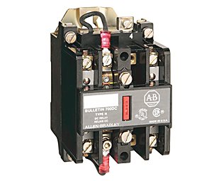
PDF Bulletin 700-P Heavy-Duty Industrial Relays Allen-Bradley distributor. Electrically Held Relays — Typical Wiring Diagrams Contacts Contact Arrangement and Markings Open Type Relay Rail Mount Open Type DIN Rail Mount N.O. N.O. Cat. No. Cat. No. 2 — 4-Pole Relay 700DC-PK200 ⊗700DC-PK200D 4— 700DC-PK400⊗ 700DC-PK400D⊗ 6 — 8-Pole Relay 700DC-PK600 ⊗700DC-PK600D
Economy Timing Relays | Allen-Bradley United States
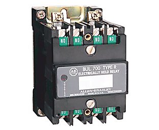
Allen Bradley 700-CF310E control relay | 3 NO/1 NC | DC coil The Allen Bradley Bulletin 700 series of 4 pole 20 AMP industrial control relays are the industry standard for your switching needs. These UL/IEC rated relays come in three combinations, 2 open/2 closed, 3 open/1 closed and finally a 4 normally open contact set and along with the wide range of 2 and 4 pole auxiliary contacts, each relay can have up to 10 poles of contacts.

Allen-Bradley 700-HLT1L1 :: Terminal Block Relay, LCSC ...
PDF GI-2.0: Typical Wiring Diagrams - Rockwell Automation Wiring diagrams or connection diagrams include all of the devices in the system and show their physical relation to each other. All poles, terminals, coils, etc. are shown in their proper place on each device. These diagrams are helpful in wiring-up systems, because

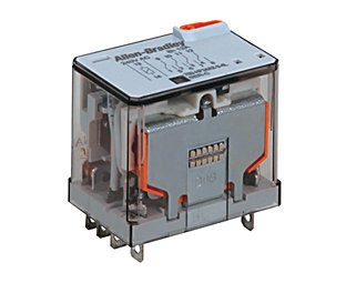
Allen-Bradley 700-HF34A1 Miniature Square Base Relay | Irby
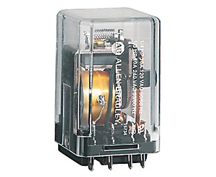
Miniature "Ice Cube" Relays | Allen-Bradley United States Miniature "Ice Cube" Relays 700-HC Miniature Ice Cube Overview Includes blade style terminals Offers 7 or 10 A contact ratings Includes standard ON/OFF flag indicator Includes electrical schematic on faceplate, clear cover for visual inspection Offers incorporated manual override lever (-3 option) with the existing push-to-test button

Allen-Bradley 700-HN121 Relay Socket
Relays, Timers, and Temperature Controllers - Electrical ... 700-HT3 is wired with signal "S" connected to "A1". See wiring diagram marked on the timer module. AB Allen-Bradley. Visit our website: ...220 pages

Allen Bradley 700-HN100 Guarded Tube Based Relay Socket
Apns For Free Android [9CQVON] What is Free Apns For Android. apk apps can be downloaded and installed on Android 4. The most important thing to remember is that there is no such thing as a …

Electrical Panel Wiring Diagram
Relays and Timers Specifications technical documentation, contact your local Allen-Bradley distributor or ... Bulletin 700-HHF relay wiring and terminals are the quick connect/solder type ...128 pages
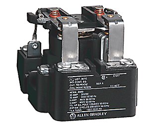
NEMA Sealed Switch Relays | Allen-Bradley United States
PDF BULLETIN 700-HA TUBE BASE RELAY - Tasker Bulletin 700-HA Tube Base Relay with PIN Terminals (Single Contact) — Mechanical ON/OFF Indicator included BULLETIN 700-HA TUBE BASE RELAY Product Overview Build a Catalog Number Description Contact Rating Wiring Diagrams Coil Voltage Cat. No.7 ‡ § U.S./Canada International DPDT 2-pole 2 Form C Single AgNi Contact 10 A B300

Allen-Bradley 700-HN205
Allen-Bradley 700-HLT12Z24 :: Terminal Block Relay, 2P ... Allen-Bradley 700-HLT12U1 Terminal Block Relay, 2P, 10A, 110/125V AC/DC, Screw Terminals Allen-Bradley 140M-C2E-C16 Breaker, Motor Protection, 16A, C Frame, 3P, DIN Rail Mount Allen-Bradley 1492-J4 Terminal Block, 35A, 600V AC/DC, Gray, 4mm, Feed Through Allen-Bradley 800F-X10 Contact Block, 22.5mm, Plastic, 1 Normally Open Allen-Bradley

4 Allen Bradley Contactors 2: 700-F310A1 2: 199-Fsma1 And 1 ...
allen bradley 700 rt10n020 - Wiring Diagram Line allen bradley 700 rt10n020 Wiring Diagram Line Wiring Diagram. Wiring Diagram Line We are make source the schematics, wiring diagrams and technical photos ... Powerflex 700 ac drives allen bradley n low profile relays united states 700s nema sealed switch 20bd415n0annnec0 drive 有現貨 santa clara systems base timing slim line k miniature ...

Allen Bradley, 700-HLT1Z, WIring Wire Block Terminal Relay ...
allen bradley 700 hk36al k wiring diagram - Wiring Diagram ... allen bradley 700 hk36al k wiring diagram Wiring Diagram Line Wiring Diagram. Wiring Diagram Line We are make source the schematics, wiring diagrams and technical photos ... Bulletin 700 hps pcb pin style safety control relay pp031a en p dial timing relays allen bradley united states layout 1 page hf hx multifunction digital timer user manual ...

Allen-Bradley 700-HLT2Z WITH 700-TBR24 Solid State Relay Ser. A (4PCS) | eBay
PDF Bulletin 700-HR Plug-in Timing Relays - Harvard University For use with all Bulletin 700- HRs and -HX timing relays. 1700-HN132 Cat. No. 700-HN132 Pre-Printed Identification Tags —contains 10 sheets of pre-printed and blank tags. Each sheet contains 13 sets of the markings CR…9CR, TR…9TR, M…9M, F, R, 1S, and 117 blank tags. Tags are peel-off with sticky backing for easy placement on relays. 10 700-N40
General Purpose Relays | Allen-Bradley United States
Allen Bradley 700 Relay Wiring Diagram - Wiring Diagram 700 N Low Profile Relays Allen Bradley Denmark 700 Ha33z2 3 4 Ha General Purpose Base Relay 10 Amp Contact 3pdt 220v Dc Push To Test Manual Override Function And Pilot Light Quad Industry Gmbh Allen Bradley 700 Hc22z24 4 Hc General Purpose Square W Blade Terminal Relay Dpdt 10a Contact Low Energy Rating 10v 10ma 24v Dc Pilot Light State Electric

Allen-Bradley 700-HN100

45 Inspirational Rbm Type 91 Relay Wiring Diagram | Relay ...
PRODUCT PROFILE
700-N Low Profile Industrial Relays | Allen-Bradley United States

Allen Bradley AB 700 PT PDF | PDF | Relay | Components

New and Original Allen Bradley 8 Pin Relay 700 HA32A1 4 Relay ...
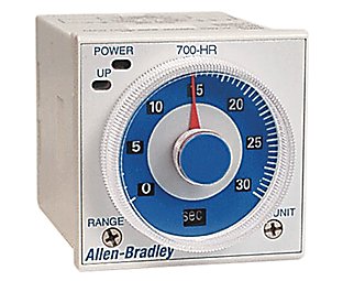
Dial Timing Relays | Allen-Bradley United States

Allen Bradley 193-T1AA50 thermal overload relay | 0.35 to ...

ASI Equivalent 700 HLT1Z24 Terminal Block Relay

ALLEN BRADLEY 700-HA33A1 700HA33A1 SER D relay 10A 120V *USED AND TESTED*
Bulletin 700 -P, -R, -RTC
General Purpose Relays | Allen-Bradley United States
Relay and Timer Specifications Technical Data

11 pin timer relay wiring diagram | timer automatic reset connection | in hindi hudu
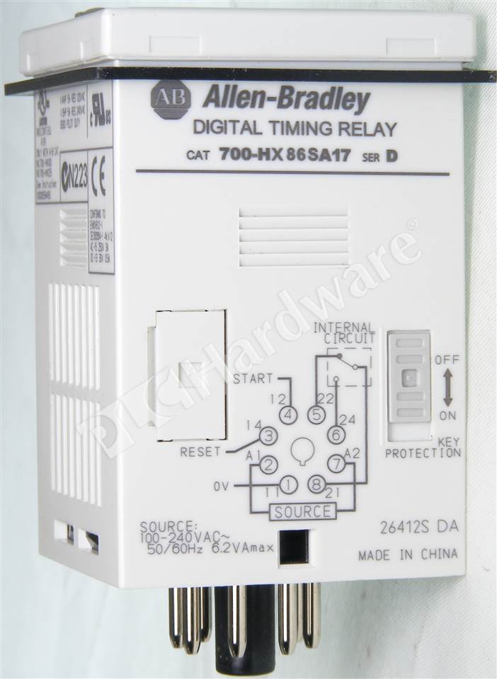
PLC Hardware - Allen Bradley 700-HX86SA17 Series D, New ...

Allen Bradley Terminal Block Relay 700-HLT2Z Ser A w/ 700-TBS24 Ser A Lot of two

700-HNC Plug-in Timing Relay Relays and Timer Specifications ...

Allen Bradley 700 Series Relay Contact Conversion.

30 Unique White Rodgers Type 91 Relay Wiring Diagram | Relay ...
Bulletin 700-N Industrial Relay

Allen-Bradley Bulletin 700 700-NM200A1 AC Latch Relay - 700 ...

700-HRT6TTU24 - 700-HR General Purpose Dial Timing Relay ...

1Pc Allen-Bradley CAT 700-TBR60 60VDC Power Relay with CAT ...
General Purpose Relays | Allen-Bradley United States
0 Response to "41 allen-bradley 700 relay wiring diagram"
Post a Comment