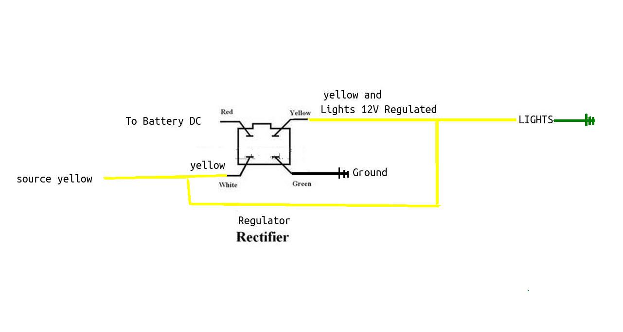
40 cycle electric regulator wiring diagram
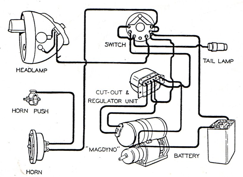
INDIAN GENERATORS - Cycle Electric Inc. com For a full 2-year guarantee use the Cycle Electric Inc. DGV-5000 generator with built in regulator Notes: 1. When replacing 65B Generator (1982-84 Hitachi) add H-D #31035-58 oil deflector. Use same gear. 2. 1936-1957 When replacing 3 brush generators use #31035-58 oil deflector, discard spring and old deflector. Cycle Electric Dgv-5000l Wiring Diagram - schematron.org WIRING. The DGV Series have two terminals marked "B" and "L". The "B" terminal is regulated power and can be connected directly to your battery or headlight switch (use 14 gage wire). If a battery is used we recommend a amp fuse or breaker between battery and generator. The "L" terminal is for your generator light.
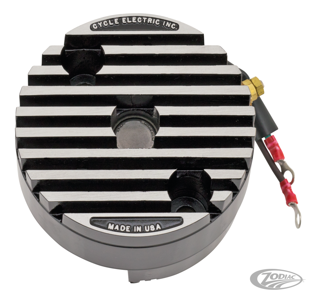
Cycle Electric Inc CE-500 SERIES REGULATORS The housing of the CE-500 series is a structural part of the generator containing one of the armature bearings. The regulator controls voltage and limits current (amps). The current limiting circuit senses armature temperature and limits the current in an inverse proportion. Temperature goes up, amps go down.

Cycle electric regulator wiring diagram
schematron.org › ezgo-rear-axle-exploded-diagramEzgo Rear Axle Exploded Diagram - Wiring Diagram Pictures Sep 20, 2018 · Trucklite 900y114 Wiring Diagram; Grundfos Circulating Pump Wiring Diagram; Msd Pro Mag Wiring Diagram; Im Icy Ferguson 135 The Wiring Diagram For The Alternator And The Regulator; 2007 F250 6.0l Power Stroke Wiring Diagram; Scotts 1642h Wiring Diagram; 3.4 Alternator Wiring Diagram Pontiac Grand Am; Mauch Pl 4-6s Bec Wiring Diagram; Ov490ea ... › 2003-ezgo-golf-cart-guide2003 EZGO Guide – Specs | Price | Manual | Wiring Diagram ... 2003 EZGO wiring diagram. A wiring diagram makes the troubleshooting process of your 2003 EZGO golf cart easy. The diagram also helps you perform some repairs and replacements on your own. The wiring diagram for the Forward/Reverse switch of an EZGO TXT Fleet golf cart is given below. These instructions cover: - Cycle Electric Inc. com Installation 1) Disconnect battery negative terminal. 2) Install oil deflector (HD# 31035-58 used on 2 brush generators from 1958-1981) gear, washer and lock nut on generator shaft. 3) Check the length of the mounting bolts. Insert a mounting bolt in the engine case. Measure from the gasket surface to the end of the bolt.
Cycle electric regulator wiring diagram. 1947 Indian Chief - Indian Motorcycle Forum One more thing. If you determine the wiring is okay you may want to replace the generator and cutout with a Cycle Electric generator (keep the original!). They have a built in regulator and work great. Depends on whether you're looking for 100 points or a rider. gpelectric.com › files › gpelectricUser Manual - Go Power 6.0 Wiring Diagram The GP-PWM-30 is based on a 30 amp max input from the solar modules. E.G. Three modules in parallel with an input of 7 amps each equal a total input of 21 amps. Most solar modules list the input amps on their specifications label. 6.1 Charging Only One Battery Use the following wiring diagram if you are using the GP-PWM-30 to Rectifier Regulator Wiring Diagram - Wiring Schemas Tutorial 5 pin rectifier regulator wiring diagram. This wiring schematics diagram is key in finding out how the charging system works on the honda cb750 k1. Simple, easy to read and to the point. You will no longer need it either. This makes the procedure for assembling circuit simpler. Lamberts bikes motorcycle part wiring diagrams. Cycle Electric Inc. com Cycle Electric Inc. will not be found responsible for damage due to physical impact, internal tampering or faulty regulation from regulators not manufactured by Cycle Electric Inc. CYCLE ELECTRIC INC 8734 DAYTON GREENVILLE PK. BROOKVILLE OH 45309 Ph. 937-884-7300 FAX.937-884-5542 For retail sales see your favorite motorcycle parts store.
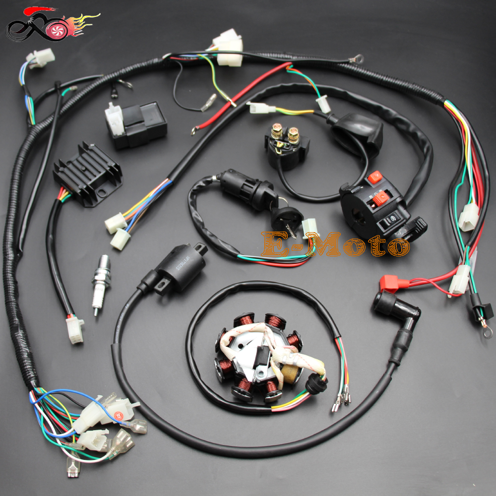
Motorcycle Regulator Diagram and Amazon: Wires V Voltage ... specification: 100% !!! size: as picture shown fitment: suitable for 50cc 70cc 90cc 110cc 125cc chinese electric start quads (only fit for 2 stroke) quantity: 1 set note: only fits 5 pins cdi,do not fits gy6 engine,which e 6 pins cdi package include: 1. quad wire harness 2. cdi 3. coil with lead 4. clter switch/remote choke 5. key switch/ 2 keys 6. ngk spark plug 7. rectifier 8. solenoid 9 ... 7 Wire Motorcycle Regulator Wiring Diagram - Database ... 7 Wire Motorcycle Regulator Wiring Diagram from static-cdn.imageservice.cloud Print the wiring diagram off plus use highlighters to trace the signal. When you make use of your finger or perhaps the actual circuit with your eyes, it is easy to mistrace the circuit. 1 trick that We 2 to printing a similar wiring plan off twice. EZGO Gas Golf Cart Wiring Diagram - 1981-1988 ... Author. HotRodCarts. Creation date. Apr 7, 2017. Tags. ezgo ezgo wiring diagram marathon wiring diagram. Overview Reviews (1) EZGO Golf Cart Wiring Diagram. E-Z-GO Wiring Diagram - Gas 1981- Early 1988. Dynamo Regulator Wiring Diagram Dynamo Regulator Wiring Diagram. To do a basic test to establish that your dynamo is working: Lucas units. Disconnect the D & F (or F2) wires from it. Make a link wire up to connect the 2. Jun 15, My regulator has three wires (1 red, 1 yellow, and 1 black with a ring connector). I have the wiring diagrams and manuals from Hoye, but I'm not.
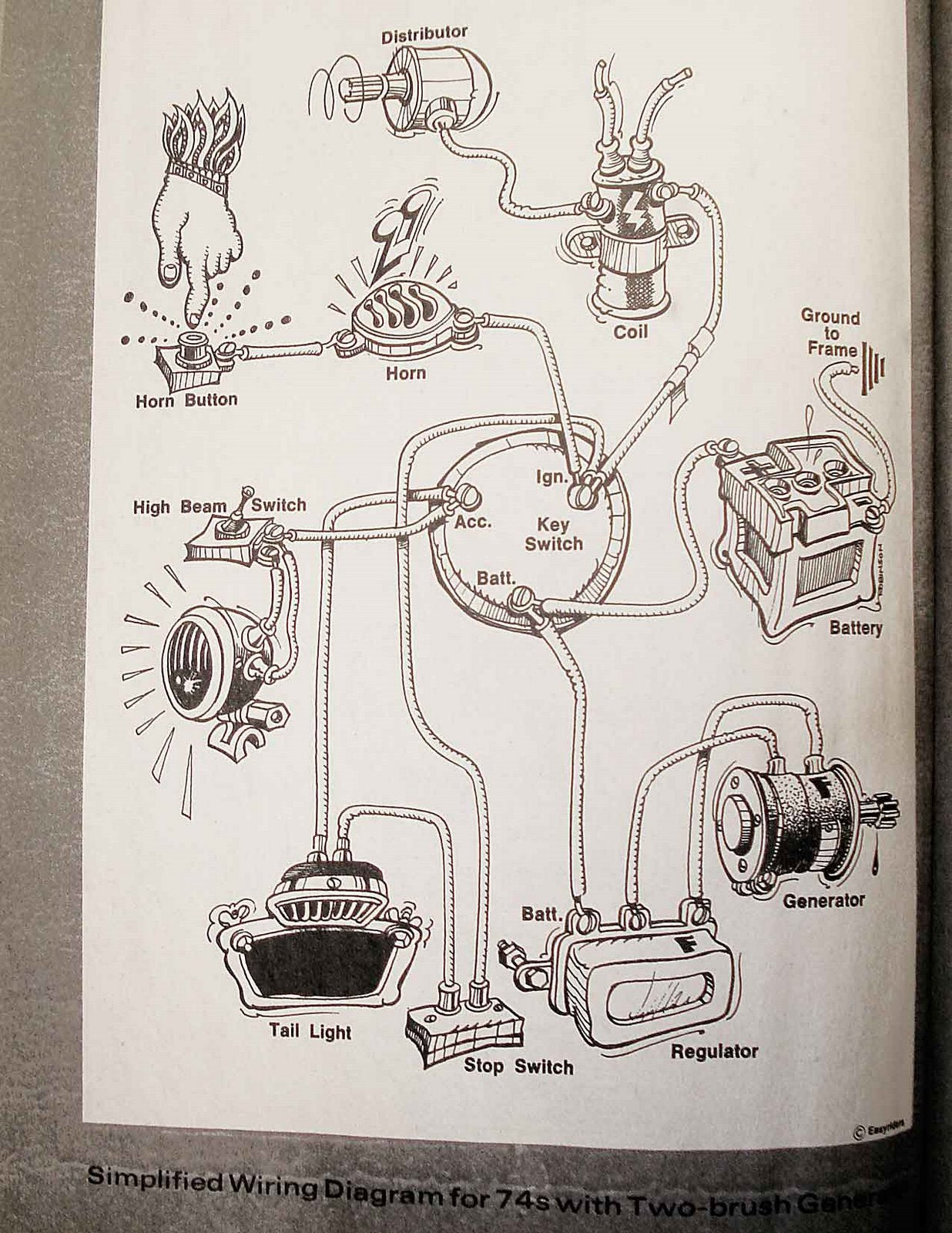
How to Wire a Motorcycle (Basic Wiring Diagrams ... Draw a diagram to map out your wires and connections. Use 16-gauge or 18-gauge insulated copper wire. Confirm you'll have enough length - do a dry run and test the length as your turn the handle bars and properly route the wires. Crimp and solder male and female bullet connectors - seal these with heat shrink wrap. Cycle Electric Generator Regulator Questions... | Jockey ... I'm finished with my build and at the point of wiring the bike from scratch using this Easy Rider diagram (minus the horn and associated wiring). Also, any tips for all wire sizes in the above diagram are appreciated. I was going to pretty much copy wire sizes in my pickup with generator and points with a new stock type replacement wiring harness. REGULATOR REMOVAL - Cycle Electric Inc. com Hold regulator in hand with fins facing down. Connect white wire on regulator to the single terminal closest to the frame screw. This terminal will have a field coil wire connected to it. Route wire between frame screw and commutater. Install a # 10 lock washer than a 10-32 nut on stud. PDF Harley Davidson Voltage Regulator Wiring Diagram now is Harley Davidson Voltage Regulator Wiring Diagram below. Clymer Harley-Davidson Shovelheads 66-84: Service, Repair, Maintenance Ron Wright 1992-09-01 Clymer motorcycle repair manuals can save you money on maintenance and repair bills. Step-by-step procedures and detailed illustrations guide you through every job, from maintenance
I keep smoking Cycle Electric Regulators any help? Set up is 64 FL w/ Cycle electric 65A generator and CE-540 regulator, stock dist, and 12v battery. Bike runs just great for a while maybe a week or so then it will act like its got a dead battery. Battery seems good holds charge no problem. When i put up a tester to the regulator its only putting out 3-6 v.
Honda Motorcycle Wiring Diagrams - Classic Cycles Honda motorcycle electrical wiring diagram schematics. Honda ANF125 Wave 125 Electrical Wiring Harness Diagram Schematic HERE. Honda C50 Super Cub Electrical Wiring Harness Diagram Schematic HERE. Honda C50M C 50 Electrical Wiring Harness Diagram Schematic HERE. Honda C65 Cub Electrical Harness Wiring Diagram Schematic 1964 - 1970 HERE. Honda C70 Cub Electrical Harness Wiring Diagram Schematic ...
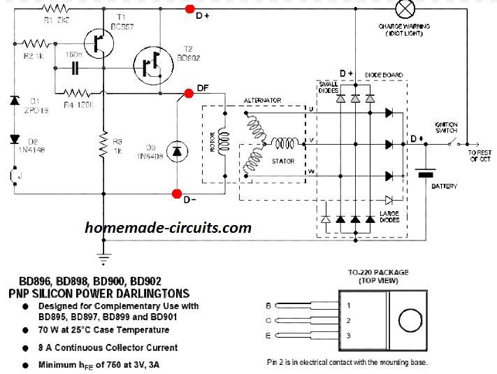
bike regulator rectifier circuit diagram - Wiring Diagram ... Bike Regulator Rectifier Circuit Diagram. 3 phase motorcycle voltage regulator circuits homemade circuit projects understanding wiring universal rectifier electrical for and boat motors diy engines online in taiwan b07l94ntsb tester building a electronics forums honda cg125 150 zj125 at affordable s free shipping real reviews with photos joom ...
Dan's Motorcycle "Wiring Diagrams" Look for the hot wire going to the turn signals. Then follow that wire color back to the battery. Now we start testing. I like to start right at the power source, the battery. With a fully charged battery and a Circuit Tester Light or an Ohm Meter, trace the voltage (6 or 12 volts) from the battery to the first connector.
Wiring Diagram Ezgo Gas Golf Cart - Wiring Diagram and ... Wiring Diagram For 1981 And Older Ezgo Models With Resistor Sd Control. Ezgo Marathon Gas Golf Cart Wiring Diagram Late 1990 93 2 Stroke Cartaholics Forum. E Z Go Gas Cart Starter Generator And Voltage Regulator Welcome To Golf Stuff Hodgepodge. Ezgo gas golf cart wiring diagram 1980 txt factory for 1981 and older basic electric 1984 marathon ...
bike rectifier circuit diagram - Wiring Diagram and Schematics 3 phase motorcycle voltage regulator circuits homemade circuit projects building a rectifier for electronics forums understanding wiring universal electrical and boat motors diy engines online in taiwan b07l94ntsb energy efficient regulating power supply fixed diagram seekic com how to test your charging system comprehensive guide motofomo mosfet full wave shunt solid state access norton bike ...
Motorcycle Wiring Simplified - The Basic Diagram ... Especially if you have a kickstarter, things can get REALLY simple, REALLY fast (i.e motorcycle wiring simplified). You can actually wire things up from scratch in about half an hour and be ready to give the bike a kick and listen. In a prior post, I go into 10 amazing pieces of advice for how to do your wiring right. That post was really ...
› en-us › automationPressure Control Regulators & Valves - Emerson Electric TESCOM™ HV-3500 Series Hydrogen Onboard Regulator designed for hydrogen fuel cell vehicles. HV-3500 Series Two Stage Pressure Reducing Regulator is designed for use onboard hydrogen fuel cell vehicles. The HV-3500 provides consistent pressure and continuous flow in a range of operating conditions.
Old School Harley Davidson Wiring Diagram - Simplified DIY ... The Wolf came up with this basic wiring diagram as he was putting this bike together from the frame up. I thought it was the coolest thing I had ever seen s...
Alternator Wiring Diagram - Wiring Diagram The Wiring Diagram is generally utilized in electric design to prepare the positioning of electric circuits. In Wiring Diagram, it is extremely vital to have at the very least one power wire and one connection cord, which are called as high-voltage line. The major feature of these wires is to lug the electrical current.
› lifanLIFAN - Motorcycles Manual PDF, Wiring Diagram & Fault Codes Hi, does anyone have a wiring diagram for lexmoto assault efi 2019, the ignition switch they sell on cmpo doesn't fit to wiring loom on bike:))). They is a 6 pin plug with red, black and brown on bike and an 6 pin plug with red, black, green, black/white on ignition switch all of them in completely different positions.
› docs › ML11229.0 GENERATOR, EXCITER, AND VOLTAGE REGULATION the '1/4-cycle' diagram. Peak output voltage is generated at each cycle point. As the armature continues to rotate, it again gets to a position of no voltage generation, shown in the ‘½-cycle diagram’. As the rotation continues, a voltage is again generated. A close examination of the wiring out of the armature reveals that the
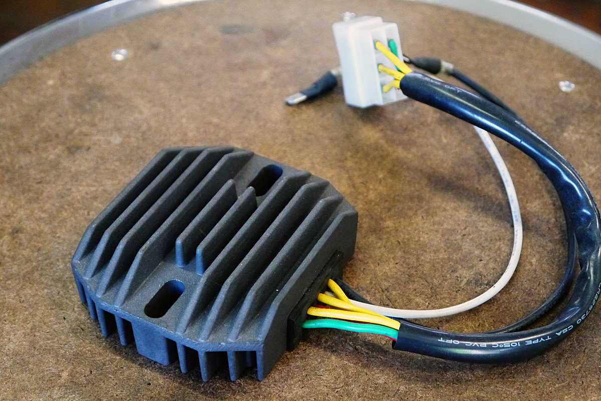
Understanding Motorcycle Voltage Regulator Wiring ... 1) 2-pin Regulator: This type may be found on some small bicycles which do not have battery and only have Head Lamp & Tail Lamp. Since the incandescent bulbs work well on AC voltage, there is no rectifier section in this type of regulator. The circuit inside the unit regulates the AC voltage coming from the generator to 13.5 - 14 VAC for the bulbs.
› 2008-ezgo-golf-cart-guide2008 EZGO Guide - Specs | Price | Manual | Wiring Diagram ... 2008 EZGO wiring diagram. A wiring diagram of your EZGO golf cart can help you gain a clear understanding of the connections in your cart. This can vary among different cart models from the same manufacturer. The wiring diagram of a 2008 EZGO MPT golf cart is found in the link given below.
These instructions cover: - Cycle Electric Inc. com Installation 1) Disconnect battery negative terminal. 2) Install oil deflector (HD# 31035-58 used on 2 brush generators from 1958-1981) gear, washer and lock nut on generator shaft. 3) Check the length of the mounting bolts. Insert a mounting bolt in the engine case. Measure from the gasket surface to the end of the bolt.
› 2003-ezgo-golf-cart-guide2003 EZGO Guide – Specs | Price | Manual | Wiring Diagram ... 2003 EZGO wiring diagram. A wiring diagram makes the troubleshooting process of your 2003 EZGO golf cart easy. The diagram also helps you perform some repairs and replacements on your own. The wiring diagram for the Forward/Reverse switch of an EZGO TXT Fleet golf cart is given below.
schematron.org › ezgo-rear-axle-exploded-diagramEzgo Rear Axle Exploded Diagram - Wiring Diagram Pictures Sep 20, 2018 · Trucklite 900y114 Wiring Diagram; Grundfos Circulating Pump Wiring Diagram; Msd Pro Mag Wiring Diagram; Im Icy Ferguson 135 The Wiring Diagram For The Alternator And The Regulator; 2007 F250 6.0l Power Stroke Wiring Diagram; Scotts 1642h Wiring Diagram; 3.4 Alternator Wiring Diagram Pontiac Grand Am; Mauch Pl 4-6s Bec Wiring Diagram; Ov490ea ...














0 Response to "40 cycle electric regulator wiring diagram"
Post a Comment