39 american rotary phase converter wiring diagram
American Rotary Phase Converter Wiring Diagram- wiring diagram is a simplified okay pictorial representation of an electrical circuit.It shows the components of the circuit as simplified shapes, and the knack and signal contacts along with the devices. Installation diagrams and videos. Rotary Phase Converter DIY. Please note that copies of wiring diagrams are usually available from your manufacturer and first, I will include a list of some owner's manuals that I found online: E-Z phase. Phase Converter from American Rotary and this is the manual. AR General Duty.
Rotary Phase Converter Wiring Diagram - 3 phase converter circuit diagram, 3 phase converter wiring diagram, 3 phase inverter circuit diagram free download, Every electric arrangement is made up of…

American rotary phase converter wiring diagram
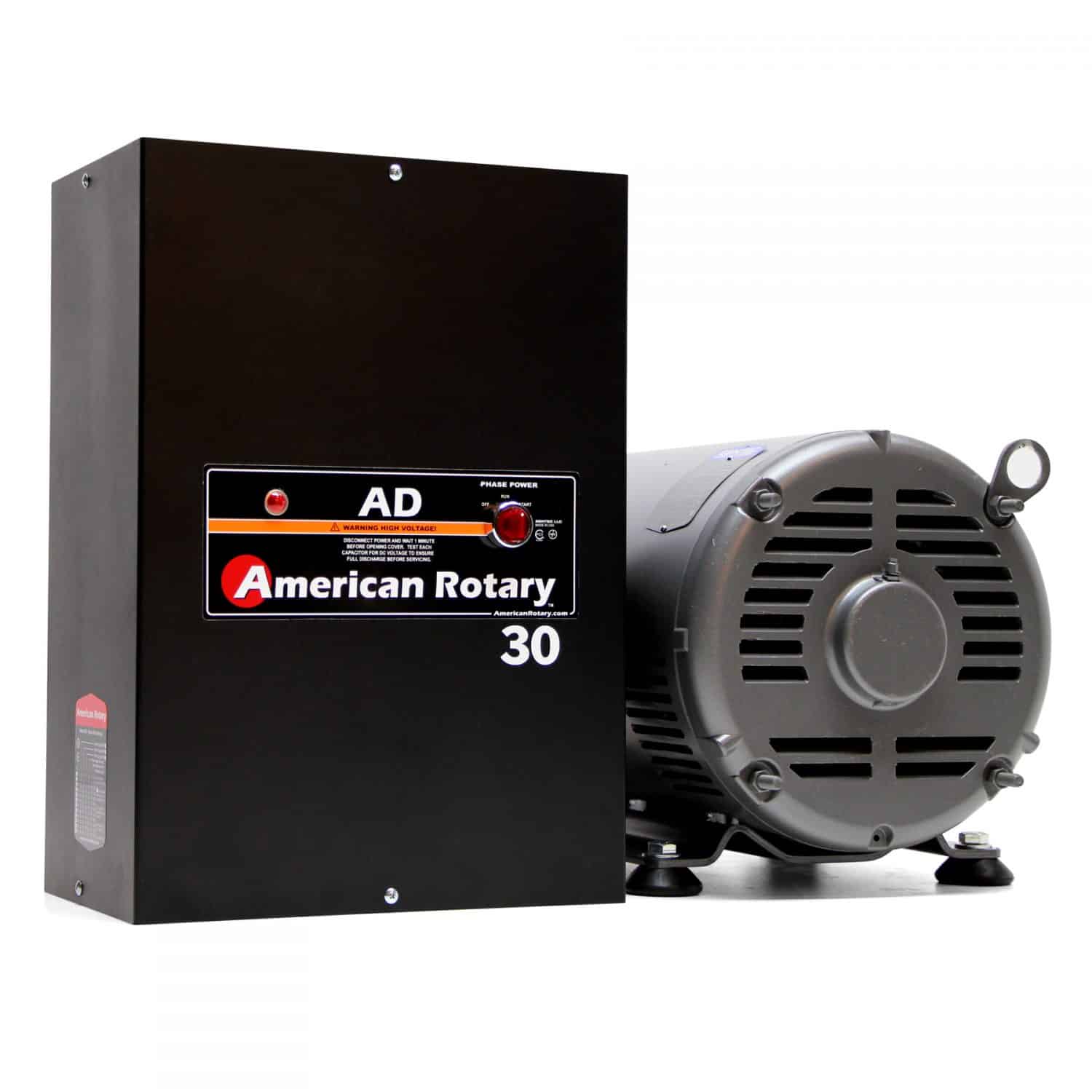
American Rotary's engineering departments spent over 2 years engineering the perfect generator for a Rotary Phase Converter, and its patent technology is the best in the industry. American Rotary's custom generator is one of a kind in our industry and outperforms the standard motor/idlers found on a typical phase converter. off, allowing you to activate any single-phase control circuits or other ... All American Rotary, rotary phase converter control panels are warranted ...25 pages off, allowing you to activate any single-phase control circuits or other ... All American Rotary, rotary phase converter control panels are warranted ...25 pages
American rotary phase converter wiring diagram. Types of Phase Converters. There are two main types of phase converters: static phase converters and rotary phase converters. Static phase converters use capacitors to help start machinery under a three-phase load. Once the machine is running, the static phase converter then disconnects, allowing the device to run on single-phase power. All our Pro Line 3 phase rotary switch wiring and phase converters include the Allen Wrenches needed for installation. All of our T1, T2, and T3 power distribution blocks are double-locks. The idler generator motor attaches to one set of holes in the power distribution block. Fifth, connect your idler generator motor. Field Wiring. Above is the field or power wiring diagram. If you look closely you will see all the basic elements from the very simple static phase converter diagram shown earlier. Contactor C1 has replaced the drum switch, and Contactor C2 has replaced the momentary pushbutton for connecting the starting capacitor between L2 and L3. In this video, we show you the basic installation techniques of the American Rotary Phase Converter Panel. The idea is to show how easy it is to install, ...
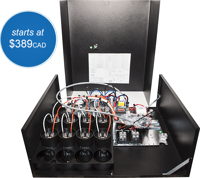
Here are some general instructions for connecting your Rotary Phase Converter: Step 1. Disconnect the power from the circuit! Step 2. Check if the circuit is disconnected with a multimeter (sorry, but this is important). Step 3. Install double pole 220 VAC breakers (for their sizes, refer to the instructions manual). • American Rotary is a 501A registered panel builder . • Built in power factor correction . • Loads can be located a large distance from the converter by simply upsizing the wire . • American Rotary phase converters should be wired by an experienced and qualified electrician into a single-phase circuit with proper breaker protection . Rotary Phase Converter Wiring Diagram. wiring diagram for loads that american rotary total up to 3 phase idler motor t1 t2 t3 wiring diagram for paralleling multiple phase converters using a transfer switch note all wiring must be done by a licensed phase a matic inc rotary phase converter installation 230v "r" series rotary converter is 230v single phase in single unit installation diagram ... All American Rotary rotary phase converter control panels are warranted against defects in material and workmanship for a period of 5 years. This warranty.5 pages
3. Rotary phase converter must start first before loads are started. 4. T3 is the generated leg, do not use for single phase loads or control circuits. 5. Do not bolt generator down solid. 6. Rotary phase converter should reach full speed within 2 to 3 seconds. ! *See Chart 2.2 for Minimum Single Phase Wire Sizes (Column C) See Chart 2.2for American Rotary's install manual for an AR-15 shows 6 gauge on the single phase side, 8 gauge on the three phase side, and 10 gauge to the idler. To be safe you should always run idler with same as incoming. You are not only drawing, you are generating. At 50-100' you should go up 1 gauge too. 12-31-2015, 09:12 AM #5. Rotary Phase Converter Wiring Diagram - 3 phase converter circuit diagram, 3 phase converter wiring diagram, 3 phase inverter circuit diagram free download, Every electric arrangement is made up of various diverse pieces. Each part ought to be placed and connected with other parts in… Rotary Phase Converter Help And Troubleshooting - Page 2 - Rotary Phase Converter Wiring Diagram. Wiring Diagram comes with a number of easy to stick to Wiring Diagram Guidelines. It is meant to aid all of the common user in building a correct program. These guidelines will be easy to understand and implement.
NAPCES Static Phase Converter Warranty. Trouble Shooting. Phase Conversion can be new to electricians, business and home owners; below are a several quick reference learning curves that we cross on a regular basis. In the rare moment of an expired component please call us for support 877-545-2926. NAPCES Rotary Phase Converter Troubleshooting.
2.1 Typical Line Diagram for Phase Converter B Rotary Phase Converter T1 & T Single Phase Power Single Phase Disconnect Switch Or Load Center Control Panel Single Phase Input L1 & L2 Three Phase Output 2 & T3 (Idler motor & load) Three Phase Loads 1. Installation must comply with all National, State and Local Electrical Codes. 2.
American Rotary Phase Converter Wiring Diagram. Collection of american rotary phase converter wiring diagram. A wiring diagram is a streamlined standard photographic depiction of an electrical circuit. It reveals the elements of the circuit as streamlined forms, and also the power as well as signal connections between the devices. A wiring diagram normally gives information about…
In this video, we show the basic installation techniques of the American Rotary Phase Converter Panel. The idea is to show how easy it is to install, 3 phase...
Installation of the American Rotary Phase Converter in a machine shop.Support the shop on Patreon:https://www.patreon.com/basementshopguyVisit me on Instagra...
Collection of 3 phase rotary converter wiring diagram. A wiring diagram is a streamlined standard photographic depiction of an electric circuit. It shows the elements of the circuit as simplified shapes, and the power and also signal connections between the tools.
The output terminals for your idler generator and loads are labeled T1, T2, and T3. Use the 3/8 inch Allen wrench supplied with the phase converter. All our Pro Line 3 phase rotary switch wiring and phase converters include the Allen Wrenches needed for installation. All of our T1, T2, and T3 power distribution blocks are double-locks.
I am finally getting my American Rotary Phase Converter installed into the new shop which will convert single phase power to three phase. At the same time, ...
Size: 113.87 KB. Dimension: 720 x 376. DOWNLOAD. Wiring Diagram Images Detail: Name: american rotary phase converter wiring diagram - 3 Phase Rotary Converter Wiring Diagram Beautiful Pretty American Rotary Phase Wiring Diagram Electrical. File Type: JPG.
American Rotary PHASE CONVERTERS Electronic/Remote blue start leads (2) (connect to 240 volt toggle switch) Three leads indicate Power Gaurd On/Off Contactor for electronic start L1 L2 T1 T2 T3 Off On (L2) (L1) (T3) T3 (manufactured line) 230 volt (three- phase panel) Off On Wiring Diagram for loads that total up to 1 times the maximum ...
All American Rotary AD & ADX rotary phase converter control panels are warranted against defects in material and workmanship for a lifetime. The American Rotary Baldor Idler / Generator is covered by Baldor's 2 year warranty. The rotor is warranted for lifetime against defects in material and workmanship to the original owner.
I'm getting a new American Rotary phase converter and that means it's time to upgrade my shop's electrical panel. I'm showing you how I do it...but if electr...
Rotary 3 Phase Converter Wiring Diagram - heretup. Collection of 3 phase rotary converter wiring diagram. A wiring diagram is a streamlined standard photographic depiction of an electric circuit. It shows the elements of the circuit as simplified shapes, and the power and also signal connections between the tools. 3 Phase Converter Wiring Diagram.
American Rotary Phase Converter Unboxing, Setup, and Wiring. Thanks to American Rotary customer, Michael Murray, we have a few videos to show you exactly what to expect when you receive an American Rotary phase converter. The unit used in these videos is an AD series model. So keep in mind, some things may vary depending on your specific order ...
phase converter is in the off position, allowing you to activate any single phase control circuits, DRO's or other single phase features on your three phase ...16 pages
American Rotary Phase Converter Wiring Diagram Gallery. american rotary phase converter wiring diagram - Architectural circuitry diagrams show the approximate areas as well as affiliations of receptacles, lighting, and also permanent electric solutions in a building. Interconnecting cord routes might be shown approximately, where specific receptacles or components need to get on an usual circuit.
off, allowing you to activate any single-phase control circuits or other ... All American Rotary, rotary phase converter control panels are warranted ...25 pages
off, allowing you to activate any single-phase control circuits or other ... All American Rotary, rotary phase converter control panels are warranted ...25 pages
American Rotary's engineering departments spent over 2 years engineering the perfect generator for a Rotary Phase Converter, and its patent technology is the best in the industry. American Rotary's custom generator is one of a kind in our industry and outperforms the standard motor/idlers found on a typical phase converter.


0 Response to "39 american rotary phase converter wiring diagram"
Post a Comment