38 betaflight f3 wiring diagram
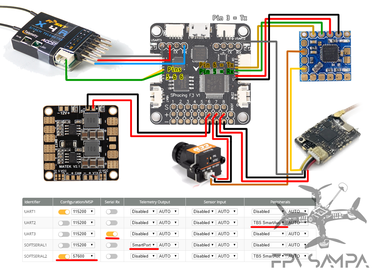
I have looked at a million wiring diagrams for connecting the SP F3 Racing board Configurations in Betaflight are correct. For sbus signal use the sbus out wire from the rxsr. How to wire a X4R-SB receiver with a SP Racing F3 Flight Controller It supports SBUS protocol; It sends telemetry data using SmartPort protocol; It is small and And the ...
This guide takes you through the full configuration of the SP F3 flight controller in BetaFlight, step-by-step. We will cover everything from installing the BetaFlight GUI software to setting up flight modes for your quadcopter. If you have been following our Beginners Guide on How to Build the Martian FPV Racing
As for the ESC, the way you have it soldered you won't be getting the current sensor, but it should work otherwise. This thread has several wiring diagrams, but a good one is right on the FPVmodel website on the BFF3 product page. The default fw is setup to handle DShot.

Betaflight f3 wiring diagram
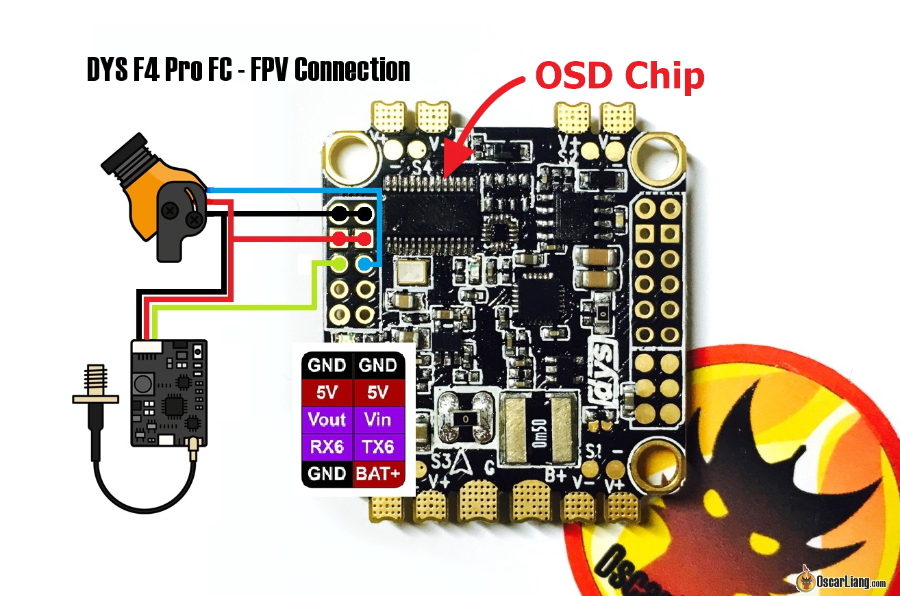
SP Racing F3 Evo to the Betaflight OMNIBUS F4 Pro /V2 Flight Control my battery lead . but looking at the diagram there are two positive. Page 1. Omnibus F4 Pro V3 Pinout. Page 2. Wiring Diagram. Page 3. The Omnibus F4 + OSD flight controller is an F4 flight controller that combines betaflights OSD which can be Firstly lets look at the ...
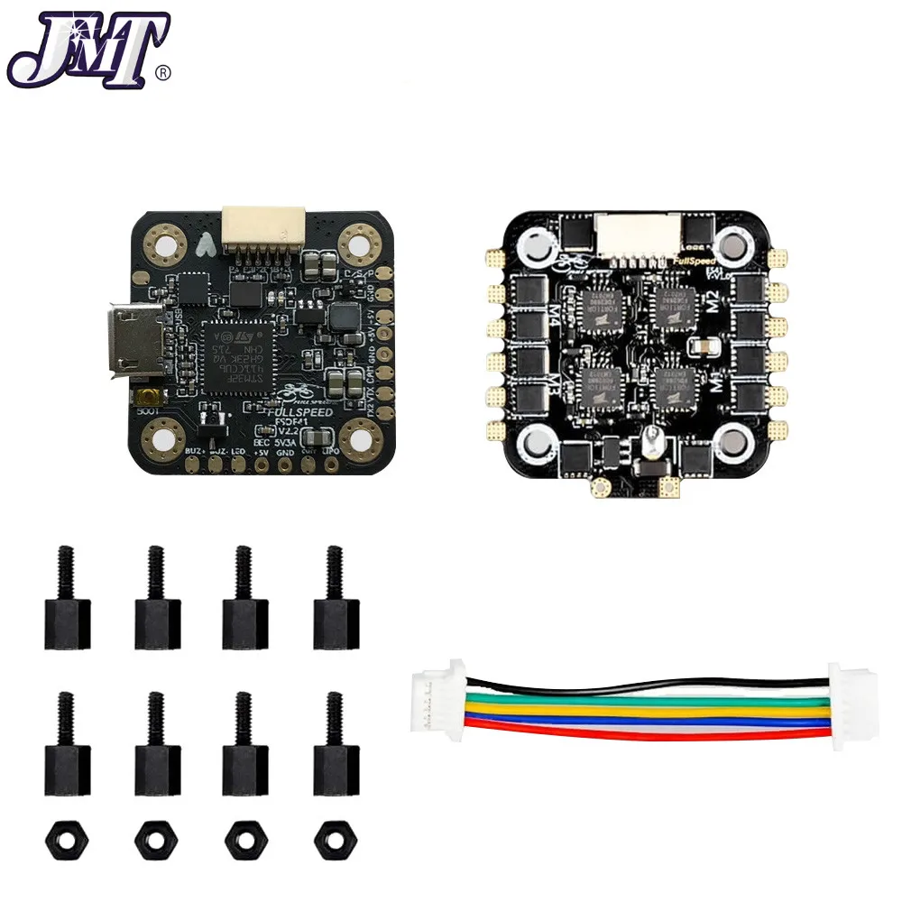
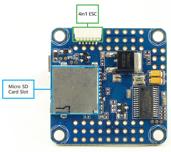
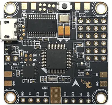
The Betaflight F3 from FPV Model is the perfect Betaflight flight controller, if what you want is an OSD, an SD card reader, and an integrated PDB. ... PCB is a more expensive design approach but was needed to give the ability to have a PDB that was capable of having wiring pads on both the top and bottom of the board. ... * Wiring Diagram ...
In this post we will explain how to setup and configure SBUS and Smart Port telemetry with F3 flight controllers on Betaflight, and F1 Naze32 FC on Cleanflight, with Frsky X4R-SB Receiver. This guide will be divided into 2 parts, first part is how to do it on a F3/F4 FC, second part is on how to do it on the F1 Naze32 Rev5 board.
Betaflight f3 wiring diagram.
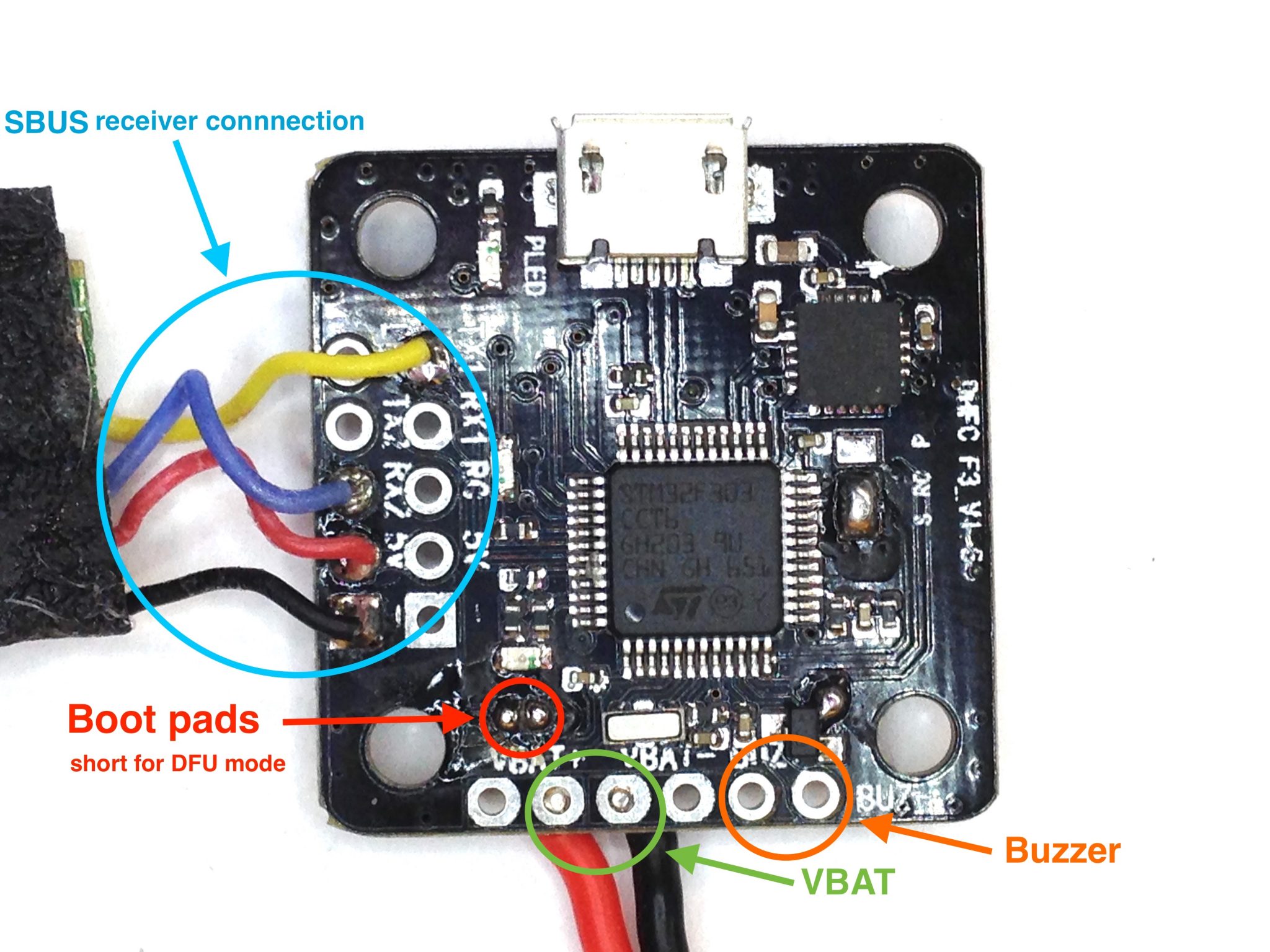
3.Download the BETAFLIGHT FIRMWARE for Crazybee F3 Flight controller from website and Open Betaflight configurator and load Local firmware 4.There are 2 ways to get in DFU Mode: 1). solder the boot pad and then plug USB to comuper 2).loading betaflight firmware and hit flash , then it will getting into DFU Mode automatically.
If you are using Betaflight, you will need an F4 or F7 flight controller. GPS function was removed for F3 boards since BF3.2 due to memory space limitation. Connecting GPS to Flight Controller. Wiring the GPS module to a flight controller is straightforward, just connect it directly to a free UART (TX to RX, RX to TX), and power it with 5V.
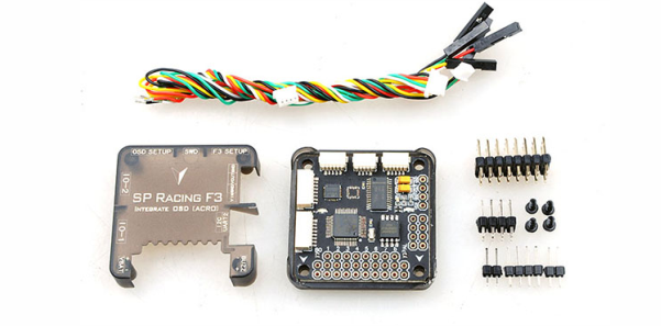
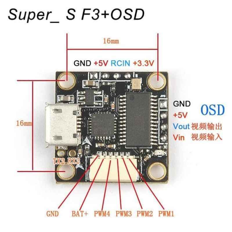
sp racing f3 drone wiring wiring diagram show. Architectural wiring diagrams ham it up the approximate locations and interconnections of receptacles, lighting, and unshakable electrical services in a building. Interconnecting wire routes may be shown approximately, where particular receptacles or fixtures must be upon a common circuit.
Betaflight F3 Wiring Diagram Free Download. A wiring diagram is a schematic type that uses abstract illustrated symbols to show all of the components of a system. Wiring diagrams are made up of two things: symbols that represent the components of a circuit, and lines that represent the connections between them.
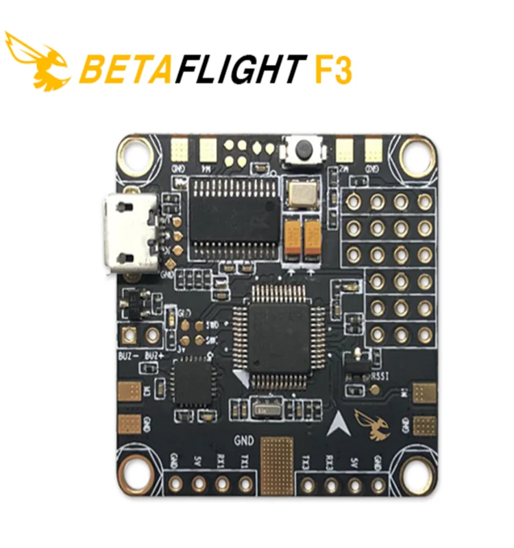
Betaflight f3 fc tanpa kasus penerbangan controller (built in osd terintegrasi pdb) untuk fpv rc drone - buy betaflight f3 pengendali penerbangan ...

Betaflight f3 fc tanpa kasus penerbangan controller (built in osd terintegrasi pdb) untuk fpv rc drone - buy betaflight f3 pengendali penerbangan ...
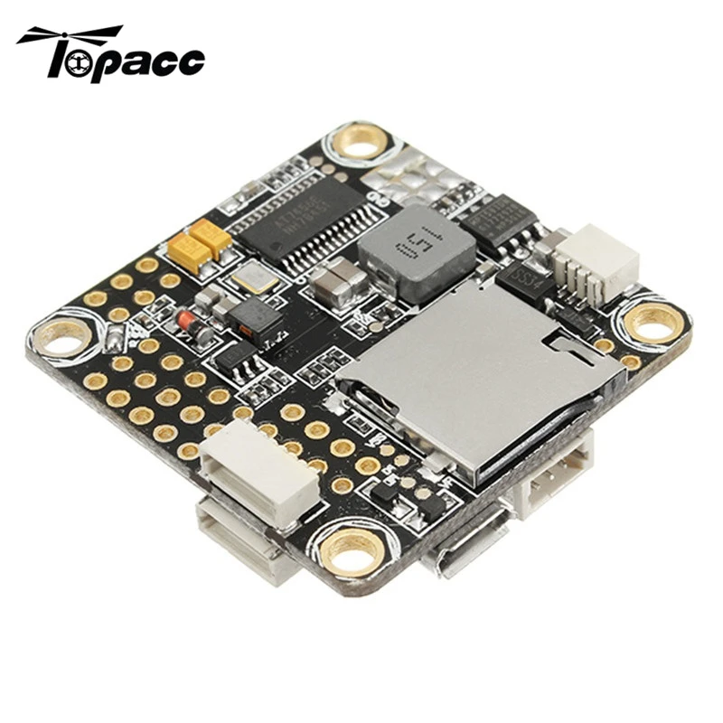
30.5*30.5mm betaflight omnibus stm32f3 f3 pro flight controller built-in osd bec current sensor for rc drone quadcopter
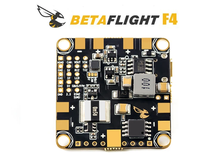
100% genuine betaflight f4 flight controller f405 processor mpu6000 gyro/acc bec max current 5v 1.5a for diy rc racing drone











0 Response to "38 betaflight f3 wiring diagram"
Post a Comment