37 solenoid valve diagram how to understand
Procedure on how to wire the electrical components in a solonoid valve, brought to you by http://stcvalve.us/CAUTION: Do not energize the coil before it is a... Pneumatic Solenoid Valve 3 Way Normally Closed 12v 24v 110v 220v Ato Com. Schematic Of Experimental Setup1 Compressor 2 Three Way Valve 3 Scientific Diagram. Pneumatic Directional Control Valves Air Or Solenoid Operated. Reading Fluids Circuit Diagrams Hydraulic Pneumatic Symbols. 3v110 1 8 3 Way 2 Position Directional Solenoid Valve.
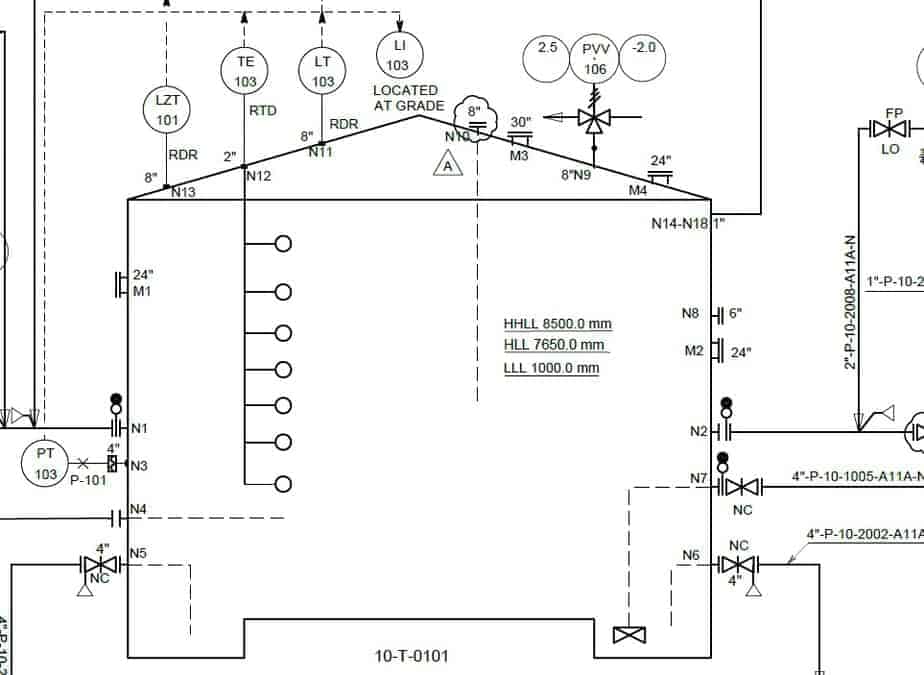
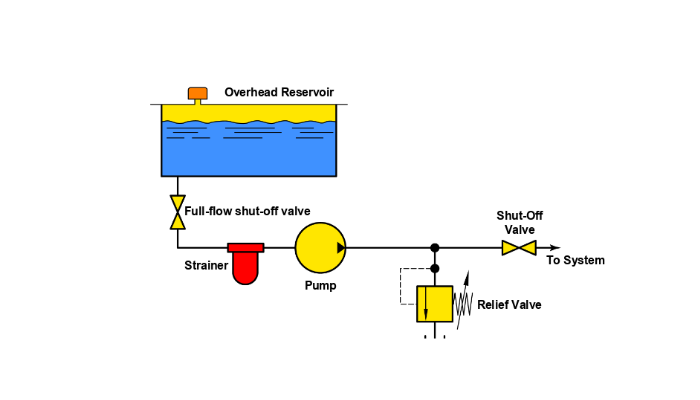
ENGINEERING FLUIDS DIAGRAMS AND PRINTS To read and understand engineering fluid diagrams and prints, usually referred to as P&IDs, an individual must be familiar with the basic symbols. EO 1.1 IDENTIFY the symbols used on engineering P&IDs for the following types of valves: a. Globe valve g. Relief valve b. Gate valve h. Rupture disk

Solenoid valve diagram how to understand
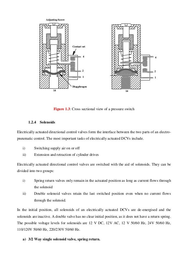
20 - Elect. operated valve (solenoid valve) 21 - Distance Relay 23 - Temperature Control Device 24 - Volts per Hertz Relay ... Basics 6 7.2 kV 3-Line Diagram : Basics 7 4.16 kV 3-Line Diagram : Basics 8 AOV Elementary & Block Diagram : Basics 9 4.16 kV Pump Schematic : ground, and at solenoid on valve in valve box. • Could be a bad solenoid (very rare). • Check to see if the water main is on. (top) These are most of the reasons why a valve is not working properly. If you have the opportunity, take a valve apart and match the parts to the attached diagram. This diagram is for Hardie / Irritrol ® solenoid valve. The spring "Pushes" from the side it is drawn on and places the right side block diagram of the valve in function. The Arrows The Arrow symbols illustrate the direction of gasses flowing into and out of the valve ports. Gas is pressure is supplied from port P. De pending on which of the valve blocks is in function, the gas is
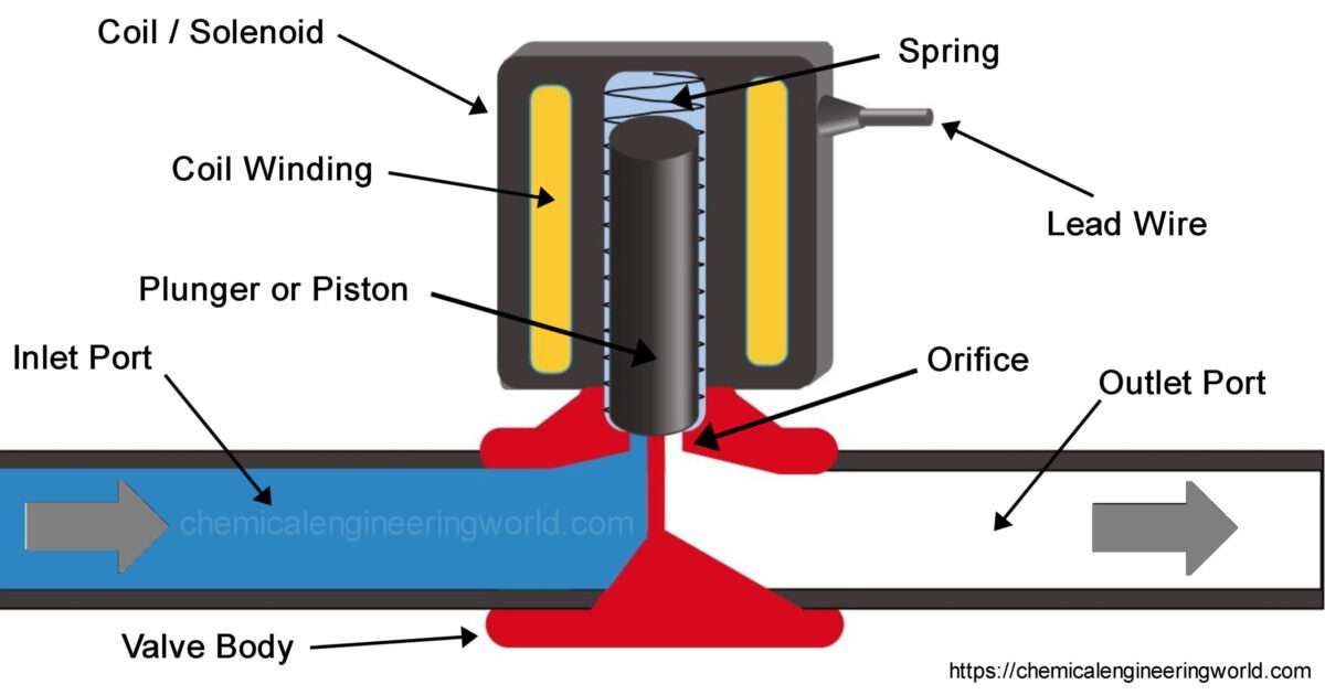
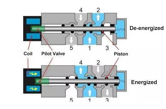
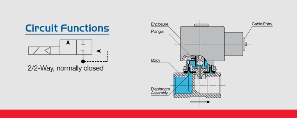
Solenoid valve diagram how to understand. Solenoid Valve - How They Work. A solenoid valve is an electrically controlled valve. The valve features a solenoid, which is an electric coil with a movable ferromagnetic core (plunger) in its center. In the rest position, the plunger closes off a small orifice. An electric current through the coil creates a magnetic field. Energizing the solenoid will cause the valve to shift to the other port. If the valve is operated by other than a solenoid or is a multiport valve, the information necessary to determine how the valve operates will be provided on each drawing or on its accompanying legend print. ... To read this diagram, a step-by-step interpretation of what is ... Let's get started. 1. Identifying the line types. In a hydraulic schematic, each line type has a unique meaning. In addition, colors can be added to indicate purpose of the line. In the figure below, all of the basic line types are shown. The basic line is a solid line that represents a working pressure hose or tube. Directional valves continue to use the square envelopes, as is seen by the 2/2 poppet valve and 4/3 solenoid valves shown. Each envelope—or square—represents one of the possible positions of the valve. The 2/2 poppet doesn't specify how the valve shifts, but that it will block flow in one position, and allows flow in the other.
8" Nugget solenoid operated valve. This valve does not have provisions for an external pilot supply which is required for "Normally Open" solenoid operated valves. Three-way valve applied to a spring return cylinder. Three-way Valves Three-way valves are the same as 2-way valves with the addition of a third port for exhausting downstream air. Understanding schematic symbols will help to better understand at a glance the application, control, direction, amount of flow for actuated valves, cylinders and rotary actuators. Basic Symbols. Square or rectangular block specify a valve position. The illustration below depicts the basic components of a solenoid valve. The valve shown in the picture is a normally-closed , direct-acting valve . This type of solenoid valve has the most simple and easy to understand principle of operation. Solenoid valves are electrically operated devices used to control flow. They are used for the remote on/off or directional control of liquids, gases and steam. They do not regulate flow. Solenoid valves consist of two main elements: 1.) An electrical coil in the solenoid, and 2.) A valve body or pressure vessel. The solenoid is the electromagnetic
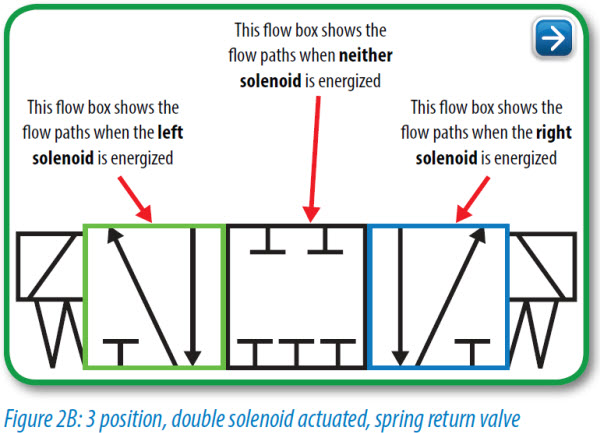
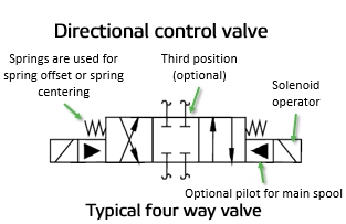
solenoid valves and the 180 solenoid pilot control...and all solenoid valves in the field that are equipped with the old style KC-2 coil. When changing from the old KC model coils to the current MKC * E34, B33, E33 and E42 are obsolete. * OE34, OB33, OE33 and OE42 are obsolete. Solenoid Valves Installation and Servicing Instructions SD-15/52021 • Understand how DHOLLANDIA diagrams are set up • Be able to recognize the used symbols, and making the link with the "real world" • Understand how the principle valves, etc… work in theory Original: 26/06/2007 ˘Last update: 24/04/2008 Learn more on our website, with this session about Flow & Directional Control Valves: https://www.lunchboxsessions.com/explore/hydraulics/flow-directional-co... The envelope that a solenoid operator is attached to is the position that the valve spool will move to when that solenoid is energized. The handle operator means that the valve can be manually operated. Spring operators indicate that the valve spool will return to its center position if there is nothing actively driving it to a different position.
Jul 25, 2003 · General Information:Valve Construction And Basic Operation. A solenoid valve is an electronically operated device. It is used to control the flow of liquids or gases in a positive, fully-closed or fully-open mode. The valve is commonly used to replace a manual valve or where remote control is desirable.

Directional Control Valve Working Animation 5 2 Solenoid Valve Pneumatic Valve Symbols Explained Youtube
The solenoid draws a continuous current of 700mA when energised and a peak of nearly 1.2A so we have to consider these things while designing the driver circuit for this particular Solenoid valve. Circuit Diagram. The complete circuit diagram for Solenoid driver circuit is shown in the image below. We will understand why it is designed so, once ...
solenoid valve. The spring "Pushes" from the side it is drawn on and places the right side block diagram of the valve in function. The Arrows The Arrow symbols illustrate the direction of gasses flowing into and out of the valve ports. Gas is pressure is supplied from port P. De pending on which of the valve blocks is in function, the gas is
Hydraulic Solenoid Valve Wiring Diagram. Print the cabling diagram off plus use highlighters to be able to trace the circuit. When you make use of your finger or stick to the circuit together with your eyes, it is easy to mistrace the circuit. A single trick that I actually use is to print the same wiring diagram off twice.
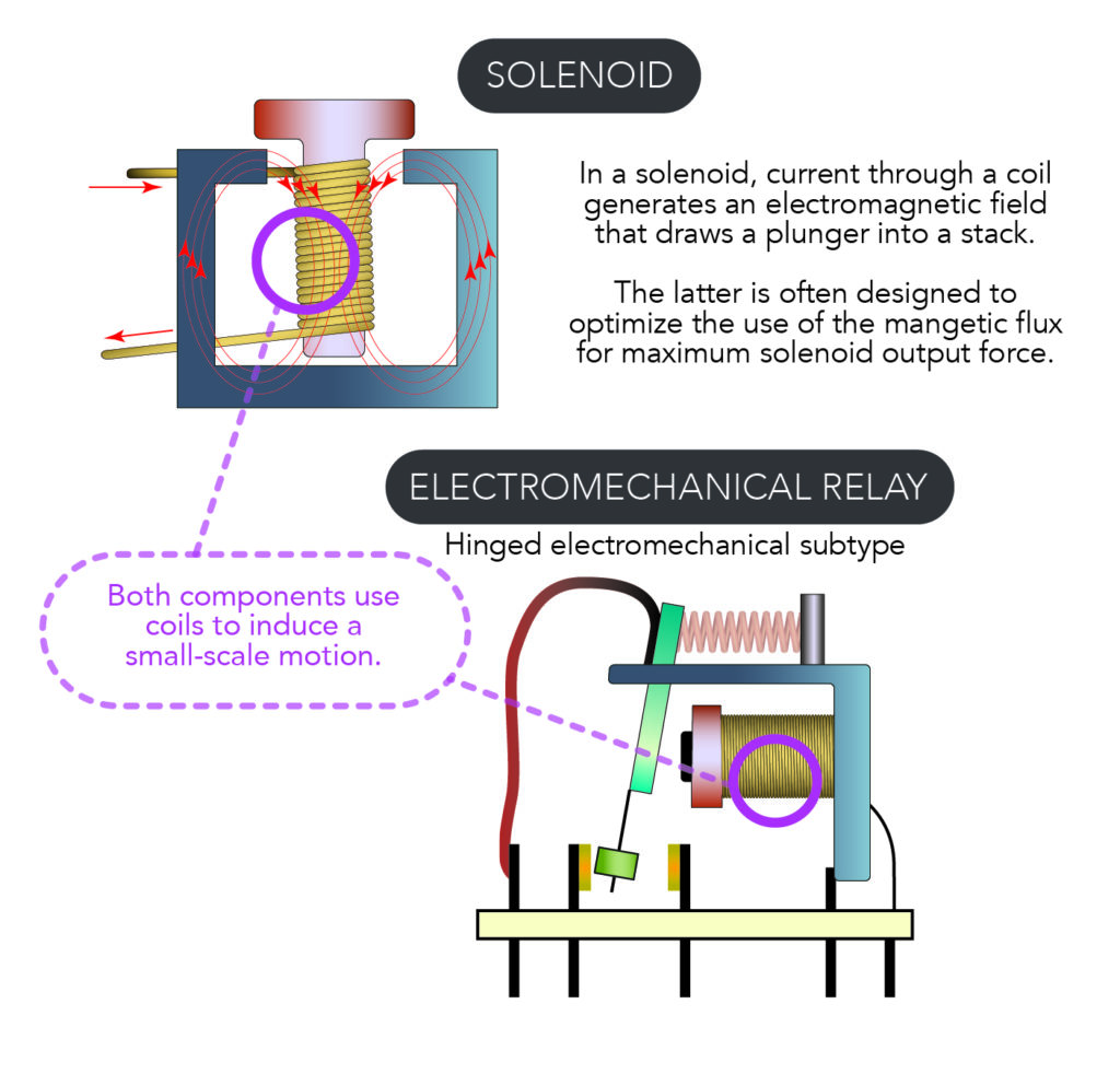
A solenoid valve is a combination of two basic functional units: • A solenoid (electromagnet) with its core • A valve body containing one or more orifices Flow through an orifice is shut off or allowed by the movement of the core when the solenoid is energized or de-energized. ASCO valves have a solenoid mounted directly on the valve body. The
The number of ports a valve has is shown by the number of endpoints in a given box. We should only count the ports in a single box once per symbol. For example, in the 3-position valve, there are three boxes that show the three possible positions, but the valve has five physical ports. So the valve will be called a 5/3 solenoid valve.
In this tutorial we will be controlling a solenoid with an Arduino and a transistor. The solenoid we have picked for this tutorial is our Plastic Water Solenoid Valve (perfect for controlling flow to a drip irrigation system) but this tutorial can be applied to most inductive loads including relays, solenoids, and basic DC motors.
Understanding Pneumatic Schematics Symbols for Sliding Solenoid Valves Return Spring indicates the Position of the solenoid valve at rest. Triangle Symbols indicate output or exhaust port B In this position Port A Is being exhausted through Arrows indicate exhaust port EA. direction of gas flow through the valve and ports
1 A solenoid is a simple form of an electromagnet consisting of a coil of insulated copper wire. A solenoid valveis an electromechanical valve frequently used to control the flow of liquid or gas. Definitions Solenoid valves are found in many applications and are commonly used in refrigeration and air conditioning systems.
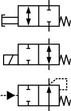
The spring symbol defines the "at Rest" position of the solenoid valve. The spring "pushes" from the side it is drawn on and places the right side block diagram of the valve in function. The T Symbol. This symbol indicates that a port is closed and is neither passing or exhausting gas. Pressure of air supply symbol.
Installation of the connector. For solenoid valve wiring, often times there is a connector. Follow these steps if the coil is fitted with a DIN-A or DIN-B connector. Use a round cable. Connect terminals (1) and (2) to the power supply. The polarity does not matter.
Solenoid valves operate using electromagnetic attraction to move the valve from the seat and most often, a spring to return the valve to the start position. This direct lift principle works well for small valve sizes or very low pressures but as valve sizes increase, the size of coil and its power consumption rises exponentially making it bulky ...
Understanding Circuit Symbols. Directional air control valves are the building blocks of pneumatic control. Symbols representing these valves provide a wealth of information about the valve they represent. Symbols show the methods of actuation, the number of positions, the flow paths and the number of ports. Here is a brief breakdown of how to ...
solenoid valve. The spring "Pushes" from the side it is drawn on and places the right side block diagram of the valve in function. The Arrows The Arrow symbols illustrate the direction of gasses flowing into and out of the valve ports. Gas is pressure is supplied from port P. De pending on which of the valve blocks is in function, the gas is
ground, and at solenoid on valve in valve box. • Could be a bad solenoid (very rare). • Check to see if the water main is on. (top) These are most of the reasons why a valve is not working properly. If you have the opportunity, take a valve apart and match the parts to the attached diagram. This diagram is for Hardie / Irritrol ®
20 - Elect. operated valve (solenoid valve) 21 - Distance Relay 23 - Temperature Control Device 24 - Volts per Hertz Relay ... Basics 6 7.2 kV 3-Line Diagram : Basics 7 4.16 kV 3-Line Diagram : Basics 8 AOV Elementary & Block Diagram : Basics 9 4.16 kV Pump Schematic :

How To Read And Interpret Piping And Instrumentation Diagrams P Id Learning Instrumentation And Control Engineering

Relief Valve Ball Valve Solenoid Valve Vacuum Breaker Hot Water Engineering Schematic Auto Part Png Pngwing
Designing A Packaging System For An Automated Lighter Package References Books 1 Croser P Ebel F Pneumatics Festo Dida











0 Response to "37 solenoid valve diagram how to understand"
Post a Comment