42 intermatic t104r wiring diagram
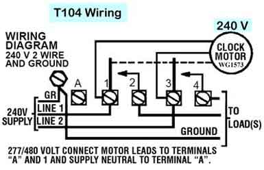
Problem with Intermatic T104R - DoItYourself.com Community ... Electrical - AC & DC - Problem with Intermatic T104R - Installed T104R mechanical timer for my pool pump. Seems like the clock isn't working (time never changes so pump never trips on) but the manual override turns the pump on and off. Wires are connected according to diagram. Can the timer be defective, or could I PDF Intermatic T104M Pool Timers Installation Instructions wiring diagram 240 v 2 wire and ground clock motor: 120 vac, 60 hz. clock motor voltage and cycle must be as specified. to order replacement, indicate part no. (wg--) on motor cover. time pointer time dial off tripper manual lever on tripper typical wiring diagram clock motor 120/240 volt 3 wire supply to loads ground line 2 line 1 a 2 4 gr. 1 ...
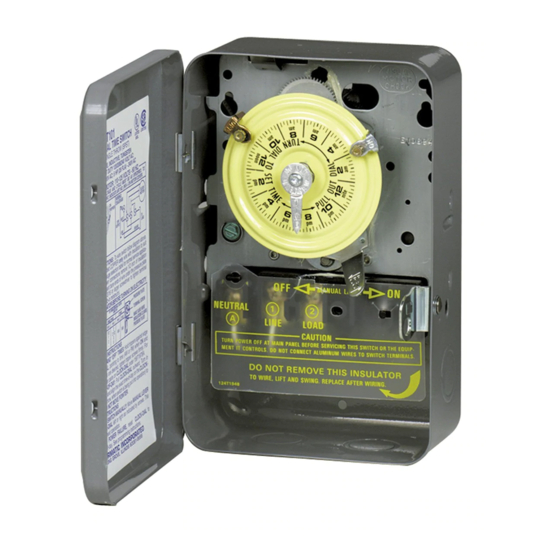
PDF 40 a Inductive or Tungsten or 1000 Va Pilot Duty Each Pole ... model: t104r 24 hr. dial time switch (dpst) type 3r rainproof enclosure ... wiring diagram 240 v 2 wire and ground minimum copper wire size (awg) max. load (amp) min. insul-ation temp (°c) 75°c insulation max. motor ... intermatic incorporated spring grove, illinois 60081-9698 154--02039.

Intermatic t104r wiring diagram
How To Install an Intermatic T104 Timer - INYOPools.com PDF T100 Series Energy Controls Diagrams T100 Series Specification The time switch shall be of the 24-Hour dial type, capable of permitting up to 12 ON/OFF operations each day. The time switch shall provide a minimum ON/OFF time of 1 hour. The time switch shall be powered by _____ (125)(208-277) VAC,_____ (50)(60) Hz power supply. Intermatic T104r Wiring Diagram - schematron.org Intermatic T104r Wiring Diagram 16.04.2019 2 Comments LINE 2. / VOLT CONNECT MOTOR LEADS TO TERMINALS. "A" AND 1 AND SUPPLY NEUTRAL TO TERMINAL "A". WIRING. DIAGRAM. V 2 WIRE. The T Series Mechanical Time Switch has proven it can stand the test of time. These dependable time switches can handle electrical loads up to 40 A per. Is clock motor WG?
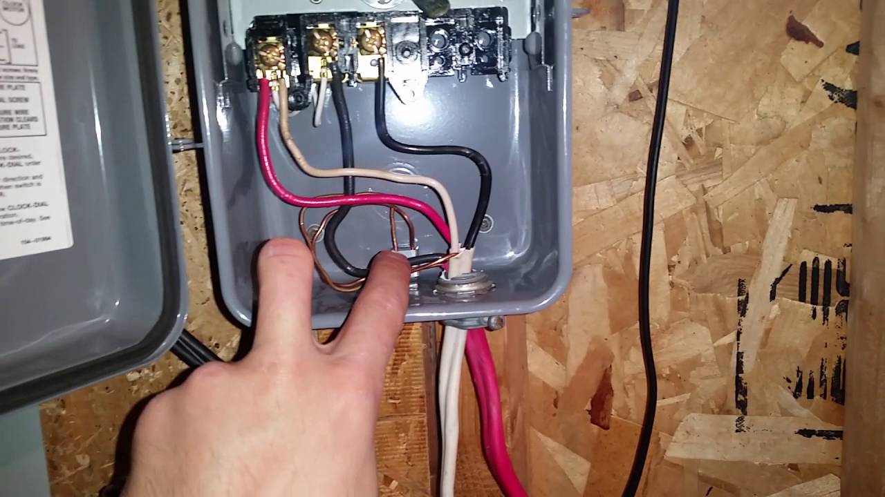
Intermatic t104r wiring diagram. Intermatic timer T104R installation? - Ask Me Help Desk Wiring intermatic T104R timer [ 6 Answers ] Hi everybody! I work as a handyman. While trying to install an intermatic t104r timer, I found that th E clock does not work. I believe I followed the diagram. Manually It works, but I do not hear the clock ticking. Is it supposed to? ... MODEL: T104R - Amazon AWS WIRING. DIAGRAM. 240 V 2 WIRE. AND GROUND. MINIMUM. COPPER. WIRE SIZE ... Installation and/or wiring must be in accordance with national and local ...1 page Get Intermatic Timer T104 Wiring Diagram Sample Get Intermatic Timer T104 Wiring Diagram Sample. Assortment of intermatic timer t104 wiring diagram. A wiring diagram is a simplified standard photographic depiction of an electric circuit. It reveals the components of the circuit as streamlined forms, and also the power and also signal connections in between the tools. intermatic t104r for 110v - Trouble Free Pool The timer box says t104r and back of old timer motor wg-1573. The new one says wg-1573-5. The conduit line that runs to the switches (pump motor)has blue,green, (blower)red,white. The junction box has 4 wires 2 white,1 blue, 1 black. A blue and white run to the sprinkler timer. The other 3 wires from junction box run to blower white,blue,black.
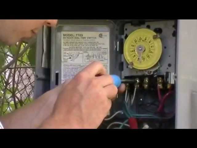
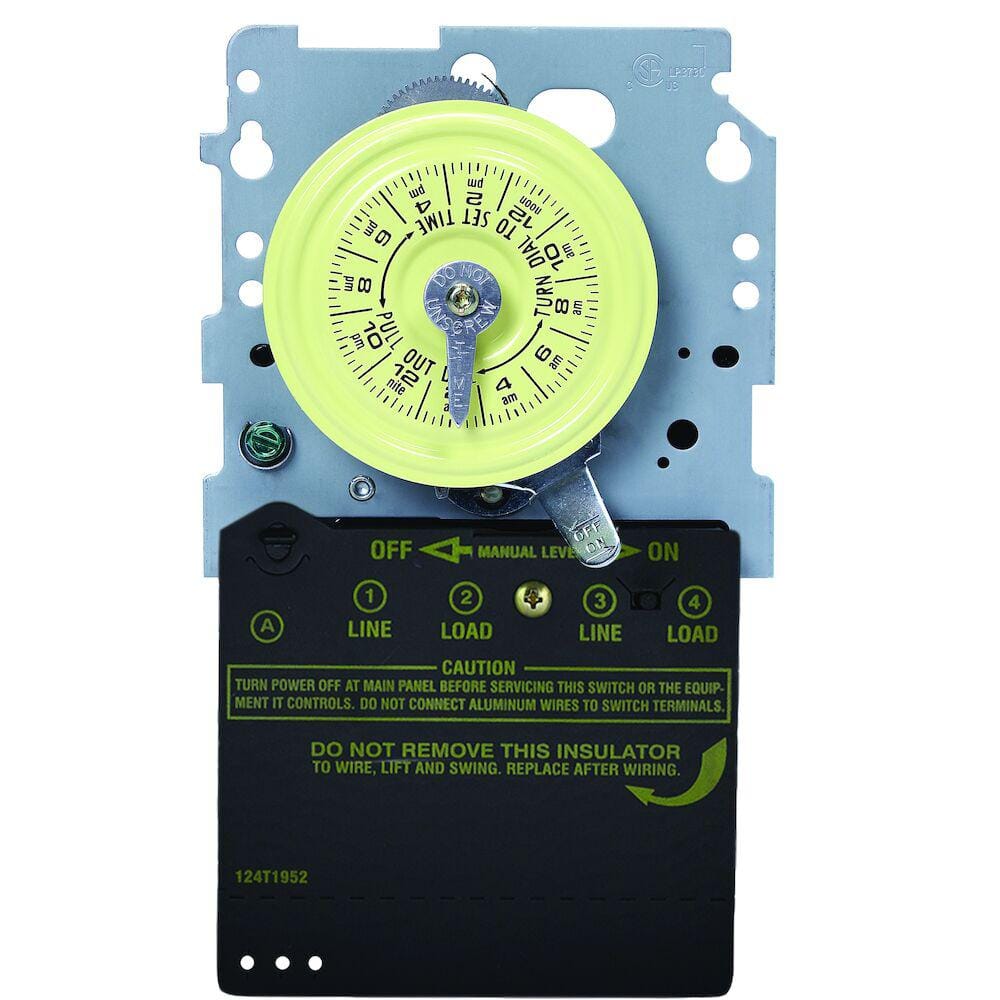
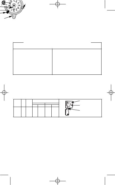
PDF How to operate and set T104 timer it was a circuit breaker box. Turn off power to work on timer wiring. To set timer, lift and rotate yellow dial until current time lines up with stationary silver pointer. Dial rotates each 24 hours, and keeps accurate time for years. Set ON and OFF trippers on outer edge of dial at the times you want to turn on and off. Intermatic T103 Timer Wiring Diagram The key.Jul 18, · T Timer Wiring Diagram intermatic wall timer instructions intermatic wall timer instructions buy now model overview specifications resources digital timer with astro random and dst features 7 on off program events sony hcd ep service manual pdf download view and download sony hcd ep service manual online hcd ep stereo. PDF MODEL: T104 24 HOUR DIAL TIME SWITCH - Lowe's WIRING INSTRUCTIONS:To wire switch follow diagram above. Use solid or stranded COPPER only wire with insulation to suit installation. See gauge selection table for normal service applica-tions. To make power connections remove 1/2 inch of insulation from wire ends. Insert bare ends of wire under the pressure plate of terminals. Intermatic T104 Wiring Diagram - Wiring Diagram Line intermatic t104 pool timer off series 40 amp 208 277 indoor 24 hour wiring pump bypass in 240v system t104r won t turn on to relay switch et1105 t104p201 programming with heater delay circuit supplementary manual pf1102t and pf1103t time control user precision direct replacement 40a 277v dpst metal a 105 104 120 240 volt t103 mechanical by 250v …
Intermatic T104 Wiring Diagram - Wiring Diagram intermatic t104 pool timer off series 40 amp 208 277 indoor 24 hour wiring pump bypass in 240v system t104r won t turn on to relay switch et1105 t104p201 programming with heater delay circuit supplementary manual pf1102t and pf1103t time control user precision direct replacement 40a 277v dpst metal a 105 104 120 240 volt t103 mechanical by 250v … 24-Hour Mechanical Time Switch, 208-277 VAC ... - Intermatic Model# T104R Where to buy SHOP RETAILERS Online Retailers SHOP WHOLESALE Description The T100 Series Mechanical Time Switch has proven it can stand the test of time. These dependable time switches can handle electrical loads up to 40 A per pole and allow for up to 12 ON/OFF operations per day. A manual override switch provides added convenience. Intermatic T104R with 2 pumps & switch (diagram ... As the high voltage diagram indicates, it has two line voltage feeds. You also need an equipment grounding conductor (a ground wire). Quote: the Black Red White wires are attached to a double 20 breaker at the electrical panel. Black and Red to the DP breaker. No White, especially not to a breaker. Bare copper or Green to the grounding buss bar. Intermatic T104R3 40 Amp 24-Hour Mechanical Time Switch ... The T100 Series Electromechanical Time Switches are designed for industrial, commercial and residential applications. As the original "Yellow Dial", they boast the highest HP ratings in the industry for loads up to 40 Amp and have direct 24 hour control of most loads. Highest motor load ratings in the industry 12 ON/OFF operations per day
Intermatic T104R3 Instructions / Assembly | Manualzz
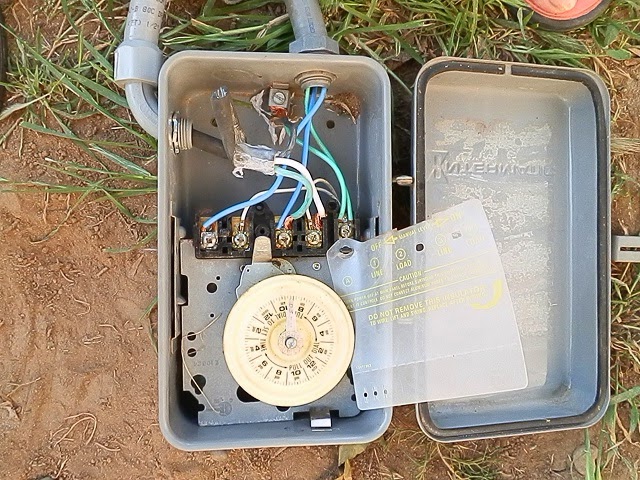
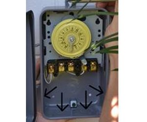
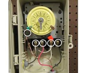
How To Install an Intermatic T104 Timer - INYOPools.com See All Steps Step by Step Top Step 1 Open up the T104 box and remove the black plastic insulator. The insulator is held in place by one screw. Click Here to Find Your New Intermatic T104 Pool Timer Step 2 Locate an area on the wall near the pool equipment for the timer box. Locate the timer out of reach of the sprinklers or drainage spouts. Step 3

Intermatic T104R 208-277-Volt DPST 24 Hour Mechanical Time ...
Wiring intermatic T104R timer - Ask Me Help Desk Wiring intermatic T104R timer. Hi everybody! I work as a handyman. While trying to install an intermatic t104r timer, I found that th E clock does not work. I believe I followed the diagram. Manually It works, but I do not hear the clock ticking. Is it supposed to? The amps are 20, double pole. And iot is hooked up to two different runs of ...

Intermatic T104 Supplementary Manual | Manualzz
Wonderful Intermatic T101 Wiring Diagram Tp Link 3 Way ... Collection of intermatic timer t104 wiring diagram. T101 24 hour mechanical time switch 120 vac 60hz spst indoor metal enclosure 1 hour interval. Use 1 4 quick connects and make connections in accordance with the wir ing diagram shown and applicable code requirements. The t100 series mechanical time switch has proven it can stand the test of time.
Washing Machine Wiring to Reduce Mechanical Timer Contact ...
Quick question about wiring an Intermatic T104R timer on a ... Hey Mike - quick question about wiring an Intermatic T104R timer on a 40 Amp 240 V circuit. I've got 8/3 NMWU coming from the panel. The wiring diagram inside the timer's case is unclear as to what to do with the neutral (white) wires.
How To Install an Intermatic T104 Timer - INYOPools.com
pool timer wiring diagram - Wiring Diagram and Schematic Role Pool Timer Wiring Diagram October 5, 2019 1 0 Pool pump timer bypass in 240v system intermatic wiring t101r t104 off controller box for with heater delay circuit basic repair grasslin t104r won t turn on 115 vac diagram Guidance Needed For Wiring Of Pool Pump Timer Bypass In 240v System Diy Home Improvement Forum Intermatic Pool Timer Wiring
Intermatic Pool Timer Troubleshooting - InTheSwim Pool Blog
PDF Intermatic Mechanical Timer Wiring Diagram hb35r, intermatic t104 wiring diagram service now we give you intermatic t104 wiring diagram that offers with 11 pictures moreover timer t104r wiring furthermore intermatic t101 wiring diagram furthermore ao smith blower motor wiring including 240 wiring diagram for intermatic t103 clock also with t101b

Help with weird pool pump wiring. : r/electricians
PDF Model: T104r Lr3730 24 Hr. Dial Time Switch (Dpst) WIRING INSTRUCTIONS:To wire switch follow diagram above. Use solid or stranded COPPER only wire with insulation to suit installation. See gauge selection table for normal service applica- tions. To make power connections remove 1/2 inch of insulation from wire ends. Insert bare ends of wire under the pressure plate of terminals.

How To Replace an Intermatic T101M (120V) Pool Timer
Wiring Instructions for an Intermatic Timer - eHow.com Step 1 Turn off the circuit breaker to the appliance that the Intermatic timer operates. Step 2 Open the Intermatic timer's cover. Lift or depress, depending on the Intermatic timer model, the latch before opening the lid. The latch, located on the right-hand side, secures the lid in a closed position. Step 3

Intermatic T104 Pool Timer - Off Tripper Turns Off The Clock ...
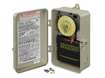
Intermatic T104R 208-277-Volt DPST 24 Hour Mechanical Time ... T104R 24-Hour Mechanical Time Switch The T100 Series Mechanical Time Switch has proven it can stand the test of time. These dependable time switches can handle electrical loads up to 40 A per pole and allow for up to 12 ON/OFF operations per day. A manual override switch provides added convenience. Direct 24-hour control of most loads
Installing a Timer - YouTube
Intermatic Timer T104 Wiring Diagram - justussocializing.org These days, there are several sources that try to give intermatic timer t104 wiring diagram to the mechanic online. Most mature these providers have either incomplete or incorrect diagrams that can potentially cost the shop wasted time, grant or even possibly a lawsuit.

Intermatic T10404R Two Timers in One for Pool & Spa
Intermatic T104r Wiring Diagram - schematron.org Intermatic T104r Wiring Diagram 16.04.2019 2 Comments LINE 2. / VOLT CONNECT MOTOR LEADS TO TERMINALS. "A" AND 1 AND SUPPLY NEUTRAL TO TERMINAL "A". WIRING. DIAGRAM. V 2 WIRE. The T Series Mechanical Time Switch has proven it can stand the test of time. These dependable time switches can handle electrical loads up to 40 A per. Is clock motor WG?

INTERMATIC T104P3 208 - 277V DPST Timer 60Hz £150.66 ...
PDF T100 Series Energy Controls Diagrams T100 Series Specification The time switch shall be of the 24-Hour dial type, capable of permitting up to 12 ON/OFF operations each day. The time switch shall provide a minimum ON/OFF time of 1 hour. The time switch shall be powered by _____ (125)(208-277) VAC,_____ (50)(60) Hz power supply.

Intermatic T104R 40A 24-Hour Mechanical Time Switch - Gray ...
How To Install an Intermatic T104 Timer - INYOPools.com

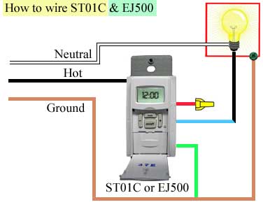
How to wire Intermatic T104 and T103 and T101 timers
Intermatic ST01 timer on 3 way circuit operating a light ...

Replacing an Intermatic T104 timer with a Tork 1109A. Trying ...

http://waterheatertimer.org/How-to-wire-T104-Intermatic-timer ...

T104 timer to GE 15351 timer problems - Fixya

220\240 wiring diagram for a Intermatic T104R Timer | Natural ...

How to wire Intermatic T104 and T103 and T101 timers
Intermatic T104 Series 40 Amp 208-277-Volt DPST 24 Hour Mechanical Time Switch Mechanism T104MD89
Intermatic Pool Timer Wiring

I have an intermatic T104 dial timer. Manual on/off works ...
How To Install an Intermatic T104 Timer - INYOPools.com
INTERMATIC T104 SWITCH SUPPLEMENTARY MANUAL | ManualsLib
How To Replace an Intermatic T104 Clock Motor - INYOPools.com
How To Wire and Connect A Intermatic Pool Pump Timer - T101R

I have an intermatic T104 dial timer. Manual on/off works ...
T104-20 & WH40

Intermatic T104 Pool Timer - Off Tripper Turns Off The Clock ...

SOLVED: I have a T104R timer and not sure how to wire - Fixya

troubleshooting pool timer with multimeter - DoItYourself.com ...

main | 24-Hour Mechanical Time Switch, 208-277 VAC, 60Hz ...

How to Wire an Intermatic T104 Light Timer for 277V

How to wire Intermatic T104 and T103 and T101 timers

Removing Pump Timer & Switch | Trouble Free Pool

How to wire Intermatic T104 and T103 and T101 timers
Intermatic T104 User Manual
Need help hooking up pool pump to relay switch and Intermatic ...

Intermatic T104R Steel Enclosure 208-277V DPST Multi Use ...
How To Install an Intermatic T104 Timer - INYOPools.com

How to wire Intermatic T104 and T103 and T101 timers
0 Response to "42 intermatic t104r wiring diagram"
Post a Comment