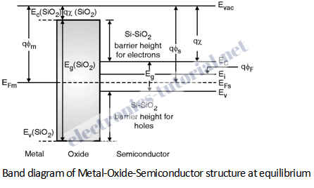
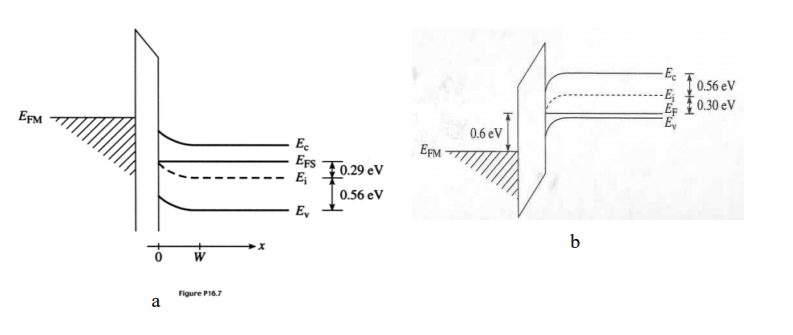
40 mos capacitor band diagram
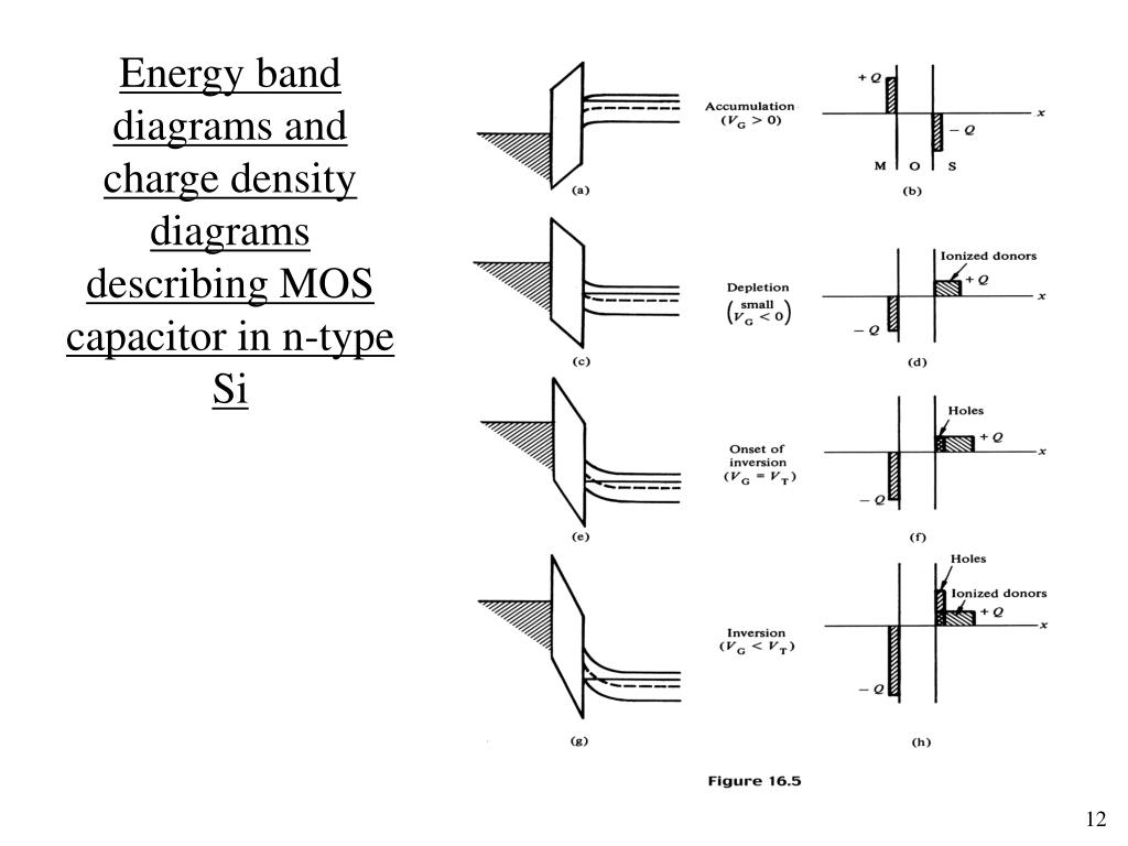
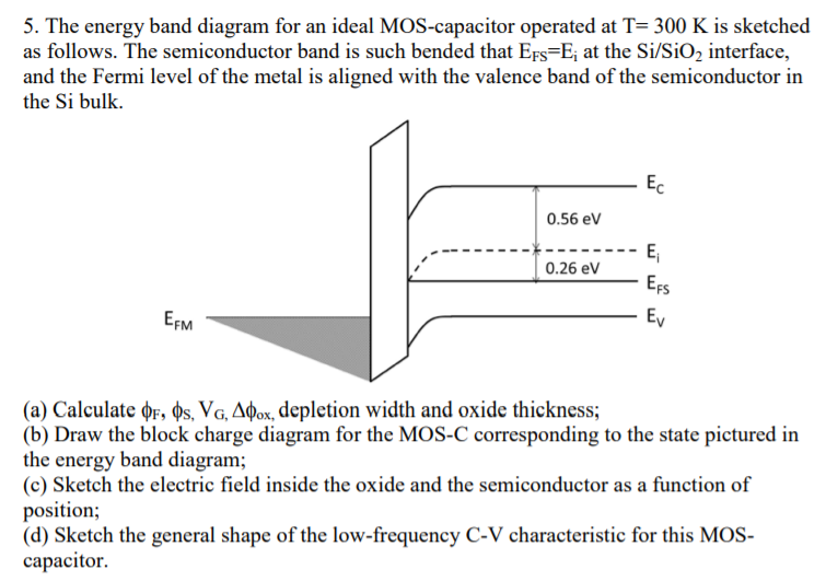
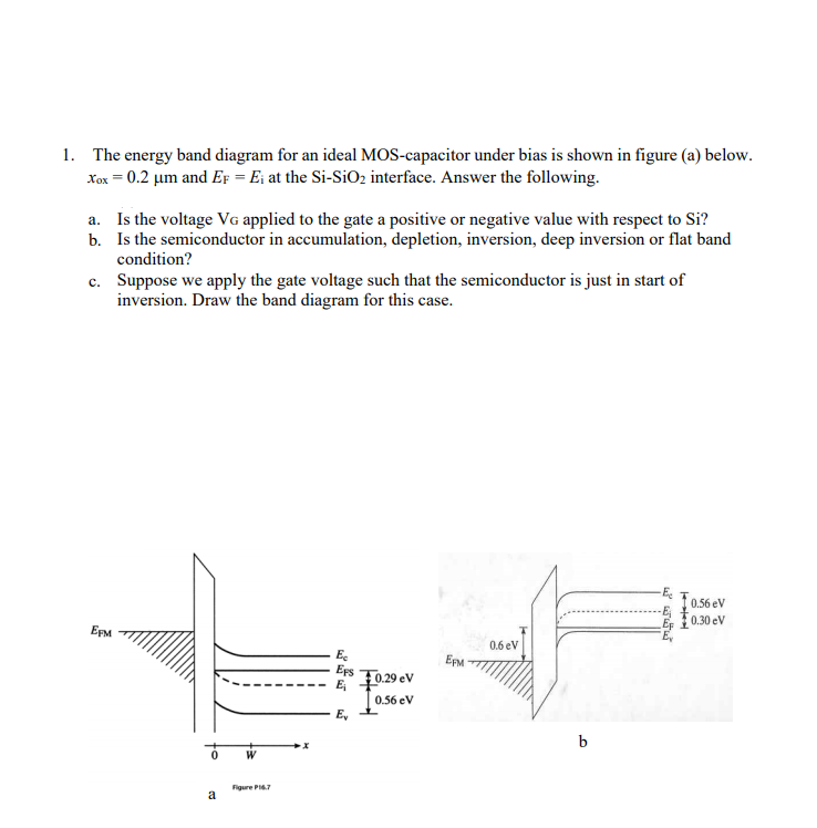
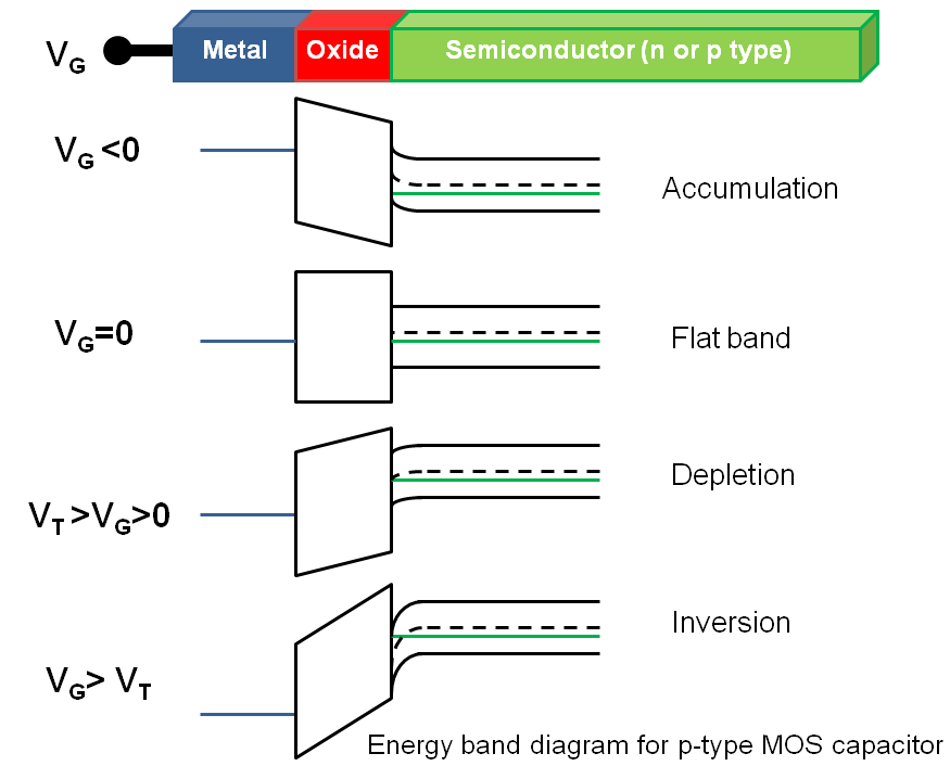
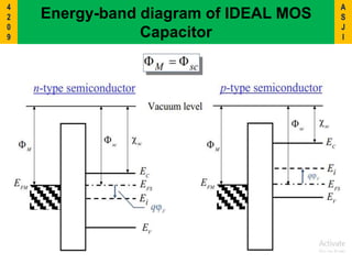
Solved 1. Draw the band diagrams of a MOS capacitor with ... Draw the band diagrams of a MOS capacitor with an n-type semiconductor in the flat-band, accumulation, depletion, and inversion states.You can assume that the metal, oxide, and semiconductor have the same work functions. Label the gate voltage, Fermi potential, and surface potential in each case. 2. PDF Chapter 1 MOSCap Tool on nanoHUB.org: A Primer Fig. 2. Energy band diagram of an ideal MOS capacitor in equilibrium. 2.1. Operation The simple band diagram as depicted above is modified when a voltage, Vg, is applied on the gate contact. Part of Vg is dropped across the oxide, Vox, and part across the semiconductor, known as the surface potential, φs.
2-1 MOS Capacitor, MOS Band Diagram - Week 2 | Coursera 2-1 MOS Capacitor, MOS Band Diagram ... contacts) week 2 Metal-Oxide-Semiconductor(MOS) Capacitor week 3 MOS Field Effect Transistors(MOSFETs) week 4 CMOS, ...4 Aug 2020 · Uploaded by Keon Jae Lee

Mos capacitor band diagram
PDF The MOS Transistor - UTEP Energy Band Diagrams Separate ... MOS Capacitor - flat band voltage Si Wafer - P type ... Energy Band Diagrams Under Bias - flat band Metal Oxide Semiconductor Surface potential is identical to bulk because of negative applied voltage. Same number of carriers across silicon now. 8 . MOS Capacitor - Accumulation ... en.wikipedia.org › wiki › Integrated_circuitIntegrated circuit - Wikipedia An integrated circuit or monolithic integrated circuit (also referred to as an IC, a chip, or a microchip) is a set of electronic circuits on one small flat piece (or "chip") of semiconductor material, usually silicon. › vlsi_design › vlsi_designVLSI Design - MOS Transistor - Tutorialspoint The following figure shows the energy band diagram of components that make up the MOS. As shown in the above figure, insulating SiO 2 layer has large energy band gap of 8eV and work function is 0.95 eV. Metal gate has work function of 4.1eV. Here, the work functions are different so it will create voltage drop across the MOS system.
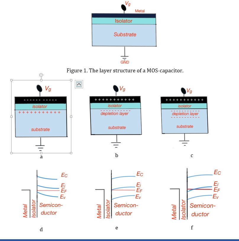
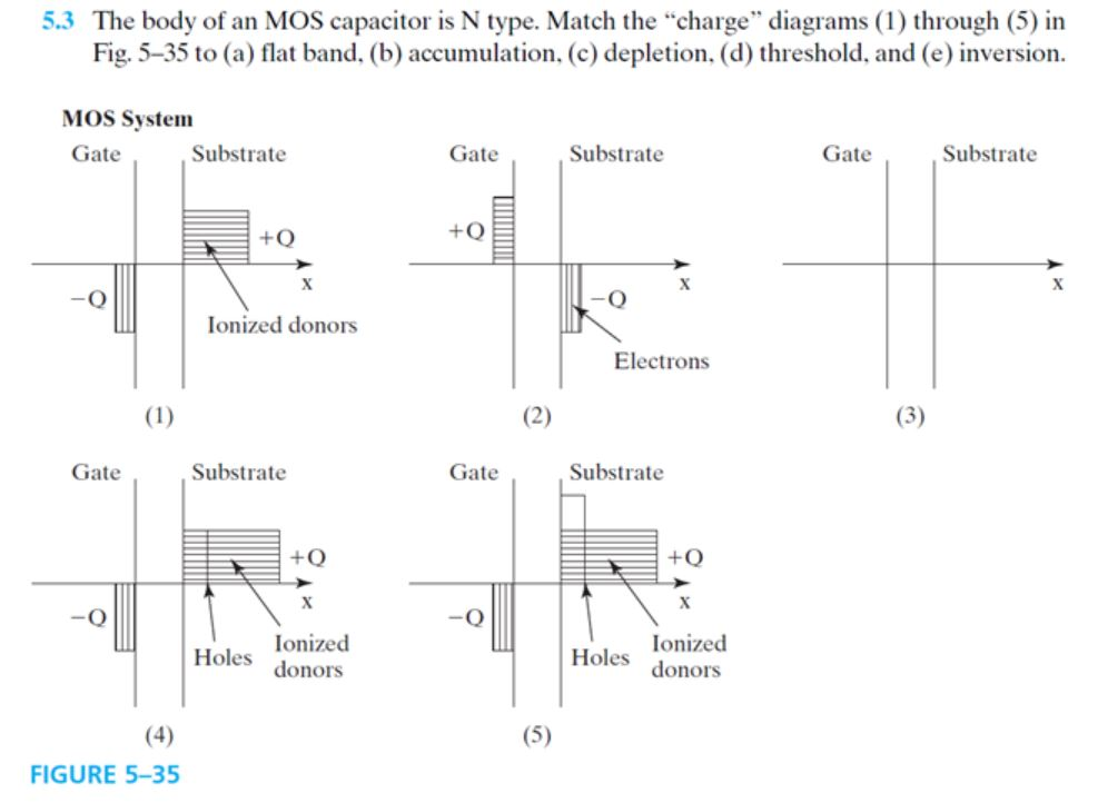
Mos capacitor band diagram. MOS Capacitor | MOS Capacitance C V Curve | Electrical4U The typical capacitance-voltage characteristics of a MOS capacitor with n-type body is given below, Capacitance vs. Gate Voltage (CV) diagram of a MOS Capacitor. The flatband voltage (V fb) separates the Accumulation region from the Depletion region. The threshold voltage (V th) separates the depletion region from the inversion region. MOS Capacitor With Energy Band Diagrams| CTQ | EC | By G.V ... In Today's video, one of the renowned and experienced faculty of MADE EASY G.V.N Ramesh Sir will help you understand, MOS Capacitor Metal Semiconductor conta... mosfet - MOS Capacitor band diagram question - Electrical ... MOS Capacitor band diagram question. Ask Question Asked 4 months ago. Modified 4 months ago. Viewed 30 times 0 \$\begingroup\$ In a MOS system, is the energy offset between metal/oxide or semiconductor/oxide always the same regardless of the gate voltage applied? In other words, are A and B in the diagram above always the same? PDF Problem: MOS capacitor Problem: MOS capacitor Draw the • charge distribution or • electric field or • band diagram (conduction band, valence band, Fermi energy) for a MOS capacitor with a • n-type substrate or • p-type substrate • in accumulation or • at the flatband condition or • in depletion or • at the threshold voltage or • in inversion.
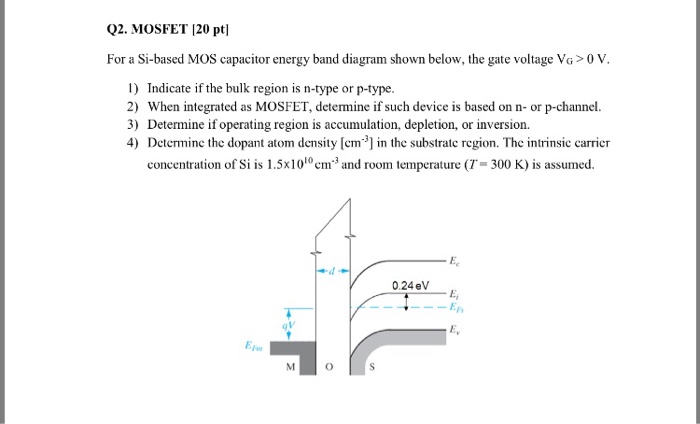
PDF MOS Devices and Circuits shows a typical structure of a MOS capacitor. The energy band diagram for ideal MOS capacitor at thermal equilibrium with zero biased voltage condition is shown in Fig. 3.1(b) and (c), whereby E F is the Fermi energy level of metal and semiconductor. E C is the conduction band of the semiconductor. E V is the valence band of the semiconductor ... PDF Chapter 5 Physics of MOSFET and MOSFET Modeling The energy band diagram of the p-type MOS device under inversion condition is shown in Fig. 5.2. Notice that inversion occurred when the surface potential is twice the Fermi ... A MOSFET is a MOS transistor and is essentially consist of a MOS capacitor and two diffused or implanted regions that serve as ohmic contacts to an ... MOS Capacitors - Electrical, Computer & Energy Engineering The energy band diagram of an n-MOS capacitor biased in inversion is shown in Figure 6.2.3. The oxide is characterized as a semiconductor with a very large bandgap, which blocks any flow of carriers between the semiconductor and the gate metal. The band-bending in the semiconductor is consistent with the presence of a depletion layer. homepages.rpi.edu › ~sawyes › Models_reviewMOSFET Device Physics and Operation Figure 1.3 Band diagrams of MOS capacitor (a) at zero bias and (b) with an applied voltage equal to the flat-band voltage. The flat-band voltage is negative in this example
B Ideal MOS Capacitor - TU Wien Ideal MOS Capacitor The band diagrams of an ideal MOS structure consisting of a gate electrode (metal or polysilicon), a dielectric (oxide), and a semiconductor (nMOS or pMOS) are shown in Fig. B.1under different operating conditions for both nMOS and pMOS. For the most simple case it is assumed that (i) there are no [Solved] The band diagram of a p-type semiconductor with a ... The band diagram of a p-type semiconductor with a band-gap of 1 eV is shown. Using this semiconductor, a MOS capacitor having V TH of -0.16 V, \(C_{ox}'\) of 100 nF/cm 2, and a metal function of 3.87 eV is fabricated. There is no charge within the oxide. wiki.analog.com › university › coursesADALM2000 Based Lab Activity Material, Electronics I and II ... A readily available enhancement mode NMOS transistor is the 2N7000. Advanced Linear Devices Inc. offers dual and quad N and P channel MOS arrays (ALD1106 and ALD1107) as well. The CD4007C CMOS logic package consists of three complementary pairs of N and P-channel enhancement mode MOS transistors. 108N. MOS Capacitor: Energy band diagram, accumulation ... Analog Circuit Design (New 2019) Professor Ali Hajimiri, CaltechCourse material at: © Copyright, Ali Hajimiri
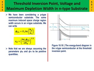
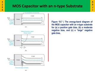
Lecture #21 MOS Capacitor Structure MOS Band Diagrams (n-type Si) • Inversion -V G< V T - Surface becomes p-type • Accumulation -V G> V FB - Electrons accumulate at surface • Depletion -V G< V FB - Electrons repelled from surface Decrease V G(toward more negative values) -> move the gate energy-bands up, relative to the Si decrease VGdecrease VG Spring 2003 EE130 Lecture 21, Slide 12
What are the energy band diagrams for an N body MOS ... Answer (1 of 3): * MOS capacitor is an equilibrium device i.e. when the external voltage is not applied to the device the Fermi level of metal and semiconductor are at same level. * When external voltage is applied to device it behaves according to the voltage applied with respect to flat band ...
PDF MOS Capacitor - Chenming Hu It is common to draw the energy band diag ram with the oxide in the middle and the gate and the body on the left- and right-hand sides as shown in Fig. 5-3. The band diagram for V g= 0 (Fig. 5-3b) is quite complex. FIGURE 5-2An MOS transistor is an MOS capacitor with PN junctions at two ends.
Band-Diagram-of-Ideal-MOS | MOS-Capacitor Digital-CMOS ... Band-Diagram-of-Ideal-MOS MOS-Capacitor Digital-CMOS-Design CMOS-Processing-Technology planar-process-technology,Silicon-Crystal-Growth, Twin-tub-Process, Wafer-Formation-Analog electronic circuits is exciting subject area of electronics.
Energy band diagram of the nMOS capacitor in the flat-band ... Download scientific diagram | Energy band diagram of the nMOS capacitor in the flat-band condition from publication: Influence of frequency and gamma irradiation on the electrical characteristics ...
PDF ECE 340 Lecture 38 : MOS Capacitor I The channel of a MOSFET is an example of a MOS capacitor… What is the structure of a MOS capacitor? •Heavily doped polycrystalline Si film as the gate electrode material. •N-type for "n-channel" transistors (NMOS). •P-type for "p-channel" transistors (PMOS). •SiO 2 as the gate dielectric •Band gap = 9 eV.
PDF Chapter 5 MOS Capacitor - University of California, Berkeley Chapter 5 MOS Capacitor MOS: Metal-Oxide-Semiconductor SiO 2 metal gate Si body V g gate P-body N+ MOS capacitor MOS transistor V g SiO 2 N+ Slide 5-2 This energy-band diagram for V g = 0 is not the simplest one. N + p o l y s i l i c o n S i O 2 P-S i l i c o n b o d y Chapter 5 MOS Capacitor Modern Semiconductor Devices for Integrated ...
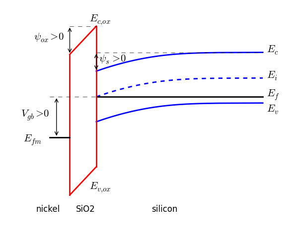
Automated drawing of the MOS band diagram The MOS capacitor's band diagram can be drawn using results from the one-dimensional solution of Poisson's equation. The accuracy of the resulting band diagram is only as good as the approximations used in the analysis. Zero gate leakage is assumed. This notebook draws the band diagram for the nickel-SiO2-Si system at an arbitrary gate-bulk bias.
nptel.ac.in › courses › 108/108/108108122NptelIitm Course Abstract. This course seeks to cover the basics of semiconductor devices including the physics of energy bands, doping and carrier statistics and transport leading up to the understanding of common semiconductor devices including p-n junctions and their applications, BJTs and MOSFETs.
Band diagram of an MOS capacitor with a positive gate bias ... Fig. 1 is a plot of an MOS band diagram for a p-substrate capacitor with a positive applied gate bias. Immediately after electron-hole pairs are created, most of the electrons will rapidly drift...
Draw and explain energy band diagram of MOS capacitor in ... Fig1 energy band diagram and MOSFET internal charge distribution in accumulation region Where E C = conduction band energy level E F = Fermi energy level E V = valance band energy level E i = intrinsic energy level Q = charge of electron V g =voltage applied on gate Φ s =surface voltage

The MOS capacitor. (a) Physical structure of an n+-Si/SiO2/p-Si MOS capacitor, and (b) cross section (c) The energy band diagram under charge neutrality.
MOS Capacitor - Solving the Poisson Equation To calculate the band bending, we start with Gauss's law, ∇ ⋅ E → = ρ ϵ s ϵ 0. Combining this with E → = − ∇ V yields the Poisson equation, ∇ 2 V = − ρ ϵ s ϵ 0, where, for a MOS capacitor with a p-type substrate, the charge density is ρ = e ( − N A − n + p) and the charge carrier concentrations are, n = N c ( 300) ( T ...
Solved 3. A. Define electron affinity in the semiconductor ... A. Define electron affinity in the semiconductor of an MOS capacitor. B. Sketch the energy-band diagram through an MOS structure with a p-type substrate and an nt polysilicon gate under zero bias. C. Define flat-band voltage. D. Define threshold voltage. 4. A. Sketch the C-V characteristics of an MOS capacitor with an n-type substrate under the ...
PDF ECE 340 Lecture 39 : MOS Capacitor II MOS Capacitor-Voltage Analysis Once we know the substrate doping, we can find the flatband capacitance… • The overall MOS FB capacitance C FB is the series combination of C debye and C i. From these values we can determine V FB the corresponds to C FB. The flatband capacitance is determined from the Debye length capacitance…
› vlsi_design › vlsi_designVLSI Design - MOS Transistor - Tutorialspoint The following figure shows the energy band diagram of components that make up the MOS. As shown in the above figure, insulating SiO 2 layer has large energy band gap of 8eV and work function is 0.95 eV. Metal gate has work function of 4.1eV. Here, the work functions are different so it will create voltage drop across the MOS system.
en.wikipedia.org › wiki › Integrated_circuitIntegrated circuit - Wikipedia An integrated circuit or monolithic integrated circuit (also referred to as an IC, a chip, or a microchip) is a set of electronic circuits on one small flat piece (or "chip") of semiconductor material, usually silicon.
PDF The MOS Transistor - UTEP Energy Band Diagrams Separate ... MOS Capacitor - flat band voltage Si Wafer - P type ... Energy Band Diagrams Under Bias - flat band Metal Oxide Semiconductor Surface potential is identical to bulk because of negative applied voltage. Same number of carriers across silicon now. 8 . MOS Capacitor - Accumulation ...












0 Response to "40 mos capacitor band diagram"
Post a Comment