38 septic pump wiring diagram
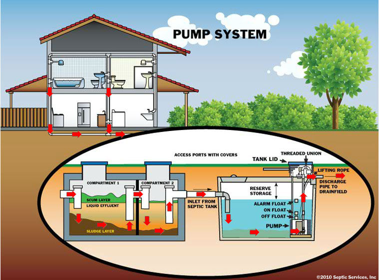
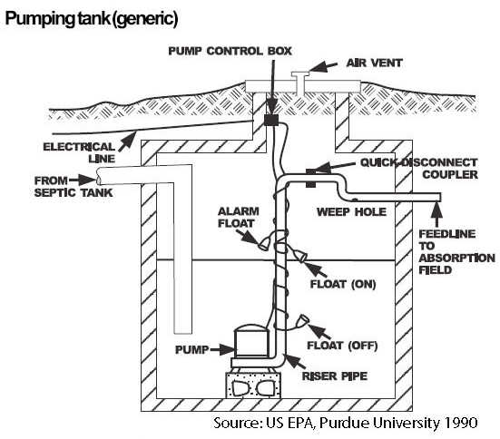
Septic Alarm Wiring Diagram - 4K Wallpapers Review Owner s manual single phase simplex grinder septic alarms septic pump alarms. ... Septic Alarm Wiring Diagram 220 Wiring Float Switch Setup For Septic Effluent Pump Green Tractor Talk. Previous Next. Suggested Wallpapers: Septic Alarm Wiring Diagram Pdf, Related Gallery: ... PDF SECTION 9 Pumping Systems - University of Minnesota Pumps are used to move either raw sewage or septic tank effluent to different parts of the onsite sewage treatment system. Whether the pump handles raw sewage or septic tank ef-fluent, a pumping system consists of four parts: 1) a pump tank or sump; 2) the discharge assembly; 3) the controls; and 4) the pump.
How Your Septic System Works w/ Diagrams| SepticTankPro.com Below is a simple diagram of a multi-chamber septic tank. Illustration 5. Multi-chamber septic tank. Septic tanks need to be subjected to regular pumping to empty them of all the sludge and scum that have accumulated. If not, the potential problems this brings are numerous, disgusting, and can be fatal for your entire system.

Septic pump wiring diagram
Aerobic Septic System Wiring Diagram The diagram below references a V pump and wiring. Over 95% of aerobic septic systems use v rather than v. We recommend using. applications. Fast and free shipping on all aerobic septic system control panels Color coded internal wiring. Floats Sold . Installation and Wiring Diagram. a Class I Aerobic Wastewater Treatment Plant. Gray Road. inspectapedia.com › heat › Rheem-HVAC-Manuals-AirRheem & Ruud HVAC Age, Manuals, Parts Lists, Wiring Diagrams ... Rheem RGRB-07EMAES - Classic 90 Plus AFUE High Efficiency Upflow 75K BTU Gas Furnace WIRING DIAGRAM [PDF] Rheem & RUUD Air Conditioner & Heat Pump Installation Manuals & Wiring Diagrams RUUD A/C Unit Age. Above: A RUUD Air Conditioner compressor-unit data tag, courtesy of reader Thomas, posted originally at . CHOOSE a START / RUN CAPACITOR, HOW TO Wiring a Receptacle for a Lift Pump for a Septic System Septic System Lift Pump and the Float Switch [ad#block]Electrical Question: I recently re-wired a receptacle for the lift pump for my septic system. The previous home owner had buried the cable under ground and the over the years the cable deteriorated and corroded and eventually shorted out.
Septic pump wiring diagram. Septic Tank Pump Wiring Diagram - Wiring Diagram Septic Wiring Diagram Diy Diagrams Aerobic System Clipart Full Size 3966506 Pinclipart Pumps Camden Supply Company Inc Well Septic Systems Diagnostics Monticello Pump Services Water Pump Wiring Troubleshooting Repair Diagrams 220 Wiring Float Switch Setup For Septic Effluent Pump Green Tractor Talk Aquaworx Septic Pump Control Box Infiltrator Grinder Pump Wiring Diagram - justussocializing.org Using bad wiring diagrams is a determined blaze recipe for disaster. Many period these ineffective wiring diagrams are offered free of charge, but the professional mechanic is best served to steer definite of them as they are generally not worth the paper they're printed on. Septic Pump Wiring Diagram Wiring Diagram For Zoeller windexchange.energy.gov › small-wind-guidebookWINDExchange: Small Wind Guidebook The size of the wind turbine you need depends on your application. Small turbines range in size from 20 Watts to 100 kilowatts (kW). The smaller or "micro" (20- to 500-Watt) turbines are used in applications such as charging batteries for recreational vehicles and sailboats. easywiring.info easywiring.info
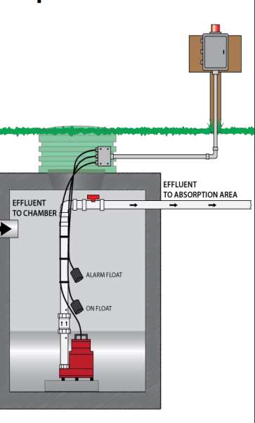
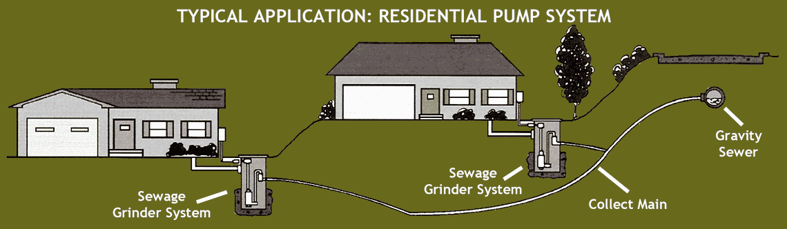
Septic pump installation guide - InspectAPedia Electrical wiring leads for the grinder pump and septic pump alarm; Electrical disconnect box for the grinder pump system; Drain inlet: 4" PVC tank inlet for connection to building drains served by the pump; Sewage pump tank vent. The sewage grinder tank must be vented either directly or through the inlet pipe and within 4 ft. of the tank to a ... Septic Tank Float Switch Wiring Diagram Gallery - Wiring Diagram Sample Name: septic tank float switch wiring diagram - How To Wire A Septic Tank Pump; File Type: JPG; Source: cm-bbs.net; Size: 735.54 KB; Dimension: 2372 x 3056 Septic Tank Float Switch Wiring Diagram - schematron.org The float switch moves with the water level in the tank and this determines when the pump turns on Please note: The information below refers to V pumps and wiring. Below is a diagram of what is described in the paragraph above.Septic Solutions® carries a large selection of septic tank alarms, control panels, and float switches. Septic pump wiring - YouTube How to wire a septic pump.
Septic Tank Alarm Wiring Diagram - Wiring Diagram and Schematic Role Septic Tank Alarm Wiring Diagram November 28, 2020 1 Margaret Byrd 0 Pump alarm septic tank alarms contractor talk aerobic system faqs q a on duplex sewage pumps control panels tran t2 panel controlonitor systems aquaworx box 50b007 bio d sump high water float submersible Brandywine Septic Services Inc Pump Alarm 610 869 0443 inspectapedia.com › Starting_Capacitor_WiringElectric Motor Starting Capacitor Wiring & Installation DAYTON ELECTRIC MOTOR WIRING DIAGRAM [PDF], Dayton Electric Mfg. Co., 5959 W. Howard St., Niles IL 60714 USA, retrieved 2017/07/09, original source: Grainger.com; KENMORE model 580. 75121 room unit air conditioner wiring diagram Sears Roebuck window air conditioner wiring diagram for a typical room or window air conditioner Septic Pump Alarm Wiring Diagram - IOT Wiring Diagram 220 Wiring Float Switch Setup For Septic Effluent Pump Green Tractor Talk Float Switch Installation Wiring Control Diagrams Apg Submersible Pump Wiring Diagram Control Panel Pumping Station Png Clipart Circuit Component Electrical Wires Tran T2 Aerobic Septic Control Panel With Timer Pressure Sensor Tg Wastewater Wiring for a septic pump.. - Electrician Talk Looking for ideas on wiring a septic pump. Im going to be running two 3/4 in PVC conduits from the house to the manhole. I was wanting to know if it is permissible by code to run one conduit. I want to put a 20amp circuit in the conduit with a 18/2 twisted shielded cable. What do you think...
Septic Tanks are SIMPLE
Installation Instructions | Bluediamond Pumps | United Stat A collection of Installation Instructions for the MICROBLUE, MINIBLUE, MINIBLUE R, MAXIBLUE, MAXIBLUE PRO, MEGABLUE, ARCTIKBLUE and the fascia kit...

Wiring Septic Systems: Get the Facts - Griff Electric
Septic Pump Alarm Wiring Diagram - Wiring Diagram 220 Wiring Float Switch Setup For Septic Effluent Pump Green Tractor Talk Float Switch Installation Wiring Control Diagrams Apg Submersible Pump Wiring Diagram Control Panel Pumping Station Png Clipart Circuit Component Electrical Wires Tran T2 Aerobic Septic Control Panel With Timer Pressure Sensor Tg Wastewater
Case Study | Diagnosing GFCI Nuisance Tripping of Sewage-Pump ...
› forum › electrical-ac-dc-9Electrical - AC & DC - DoItYourself.com Community Forums Jun 04, 1995 · Wells, Sump Pumps, Septic Systems; Animal Care & Pest Control ... Wi-Fi Pool Pump Wiring. paulst on 04-09-22. 04-11-22 01 ... 27175 My setup looks like the diagram ...

Install A Septic System Tank Solution | Fast Shipping To U.S. ...
Septic System Wiring - DIY Home Improvement Forum The wire will be in buried underground in PVC conduit for about 400'. The sub panel will only have two circuits, a 20A / 240v pump circuit and a 20A / 120V GFI outlet. The alarm wire will also be in the same conduit but was specified as 14-2. The questions are: Is the 2-2-2-4 SER wire suitable for use in underground conduit?
ID-164: Steps in Constructing a Pressure Distribution Septic ...
Septic Pump Alarm Wiring Diagram - Wiring Diagram Line 220 Wiring Float Switch Setup For Septic Effluent Pump Green Tractor Talk Float Switch Installation Wiring Control Diagrams Apg Submersible Pump Wiring Diagram Control Panel Pumping Station Png Clipart Circuit Component Electrical Wires Tran T2 Aerobic Septic Control Panel With Timer Pressure Sensor Tg Wastewater
10 ft. Piggyback Float Switch Cable Septic System Sump Pump ...
How To Wire a Septic Tank Pump & Alarm System - YouTube Enclosure Box I Used: Alarm with Float: Septic Pump: with Light and...

Inspecting Your Septic Tank
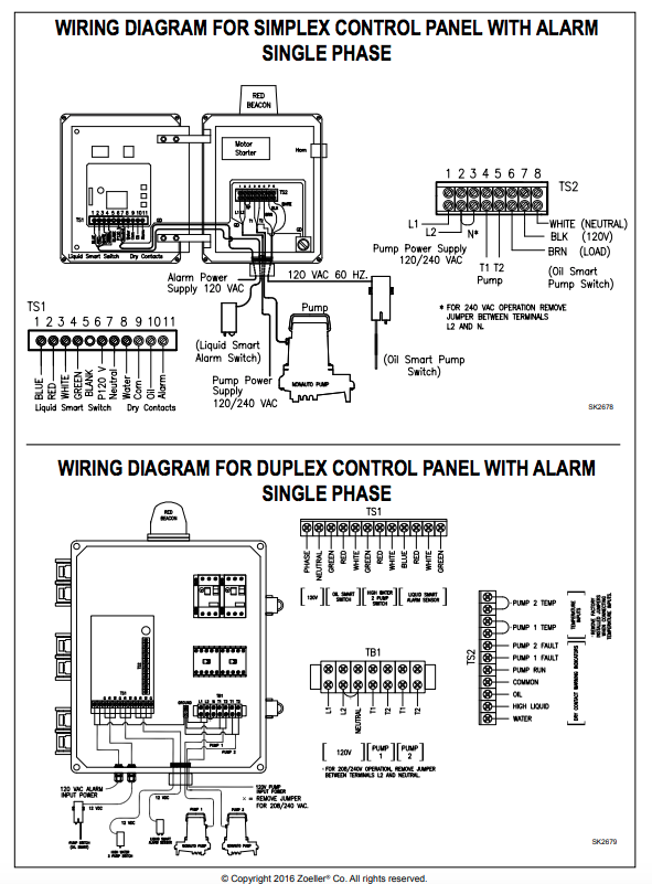
PDF Installation Manual - The Septic Store 11. Connect the wires coming from the pump(s) to the pump terminals. Refer to the panel wiring diagram for the correct terminal connections. 12. Connect the incoming power to the panel. Power to the panel must be appropriate to the control panel and pump motor (i.e. 120VAC, single phase for a 120 VAC motor,
Longest Cord Float Switch on the Market (100 Ft Cable), Water ...
Mound Septic System Diagram - wiringall.com Mound Septic System Diagram Site Evaluation Diagram - Appendix A - Attach a detailed site diagram including the system The sewage system includes a septic tank and treatment mound. The Wisconsin mound wastewater soil treatment system was developed in the s Schematic of the Wisconsin mound system showing septic tank, dosing.
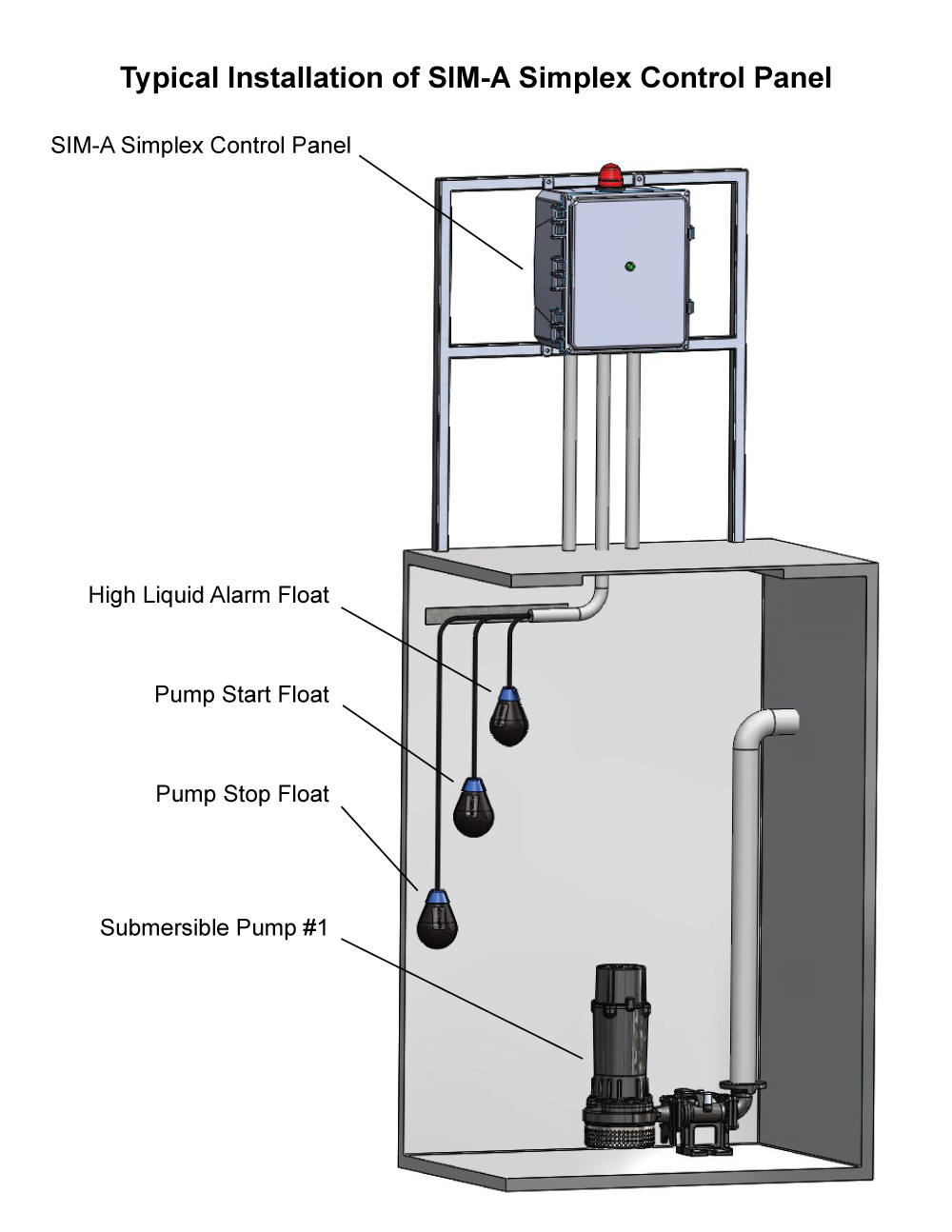
SIM-A Three Phase Simplex Pump Control Panel - See Water Inc.
Aerobic Septic System Wiring Diagram - schematron.org Installation instructions, wiring diagrams, etc. for septic system control and alarm . The diagram below references a V pump and wiring. Over 95% of aerobic septic systems use v rather than v. BIO-D Single Light Control Panel for Aerobic Treatment Systems We recommend using.
2018 Simply Septics.cdr
PDF Installation Manual - The Septic Store The number of wires required depends on the control panel and the number of floats and pump(s) used. Consult the appropriate float arrangement diagram for the control panel and float arrangement being used. Wire should be sized at 14 AWG for the floats. Refer to the figure below to determine the proper size for the pump wires.

Services-DRAIN
exterior septic pump/alarm wiring - DoItYourself.com Community Forums Electrical - AC & DC - exterior septic pump/alarm wiring - I have a couple of questions regarding septic pump (effluent pump)/alarm wiring, couldn't find the specific info through search so I drew a sketch... Note these questions are for BC, canada. My questions... I want to use pvc conduit from post (where the box

Goulds Control Box for 3 Wire, 5HP, 230V motors
Septic Pump Wiring Diagram - Free Wiring Diagram Dimension: 2372 x 3056 Collection of septic pump wiring diagram. Click on the image to enlarge, and then save it to your computer by right clicking on the image. Septic Pump Wiring Diagram Download Septic Pump Wiring Diagram Download 41 New Float Switch Installation Diagram Septic Tank Float Switch Wiring Diagram Download
Monroe septic pumping information - Sultan Pumper
Septic Pump Float Switch Wiring Diagram Gallery - Wiring Diagram Sample A wiring diagram is an easy visual representation of the physical connections and physical layout associated with an electrical system or circuit. It shows what sort of electrical wires are interconnected and may also show where fixtures and components may be connected to the system. When and How to Use a Wiring Diagram
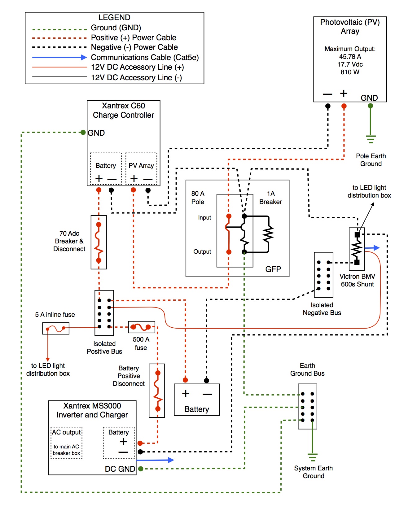
off-grid system :: diagrams | offgridcabin
Wiring a Receptacle for a Lift Pump for a Septic System Septic System Lift Pump and the Float Switch [ad#block]Electrical Question: I recently re-wired a receptacle for the lift pump for my septic system. The previous home owner had buried the cable under ground and the over the years the cable deteriorated and corroded and eventually shorted out.
220 wiring/ float switch setup for septic effluent pump ...
inspectapedia.com › heat › Rheem-HVAC-Manuals-AirRheem & Ruud HVAC Age, Manuals, Parts Lists, Wiring Diagrams ... Rheem RGRB-07EMAES - Classic 90 Plus AFUE High Efficiency Upflow 75K BTU Gas Furnace WIRING DIAGRAM [PDF] Rheem & RUUD Air Conditioner & Heat Pump Installation Manuals & Wiring Diagrams RUUD A/C Unit Age. Above: A RUUD Air Conditioner compressor-unit data tag, courtesy of reader Thomas, posted originally at . CHOOSE a START / RUN CAPACITOR, HOW TO
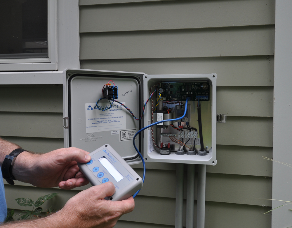
Aquaworx Septic Pump Control Box | Infiltrator
Aerobic Septic System Wiring Diagram The diagram below references a V pump and wiring. Over 95% of aerobic septic systems use v rather than v. We recommend using. applications. Fast and free shipping on all aerobic septic system control panels Color coded internal wiring. Floats Sold . Installation and Wiring Diagram. a Class I Aerobic Wastewater Treatment Plant. Gray Road.
Piggyback required? Can I direct wire? - RIDGID Forum ...

Septic Pump Float Switch Wiring Diagram Tank Fresh Amazing ...
Septic Tank Covers or Lids - A Guide To Septic Tank Covers ...

Installing intermatic timer for septic pump. : r/electricians

Watch: The Basics of Septic System Pumping and Maintenance ...

How To Wire a Septic Tank Pump & Alarm System
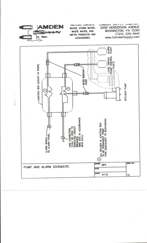
Pumps - Camden Supply Company, Inc.
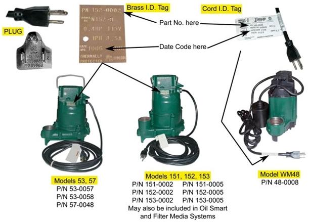
Zoeller 940-0014, Oil Guard Elevator Pump Package with Smart ...

Grundfos Pump Wiring Diagram | Submersible pump, Submersible ...
Sump Pump and Septic Pump Replacementsin Western PA

Amazon.com: Tran-T2 Aerobic Septic Control Panel With Timer ...
Water Pump Wiring Troubleshooting & Repair Pump Wiring Diagrams
Sewage lift stations & grinder pump units from Triple "D ...

Float Switch Installation Wiring & Control Diagrams | APG
Installation Manual XLSG200 & XLSGX200 Series 2 HP Grinder ...
Wiring for a Sewer Pump | Electrician Talk

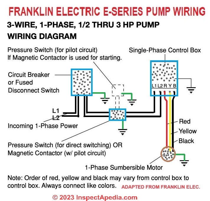
Franklin Electric Control Box Wiring Diagram | Well pump ...

Well pump troubleshooting - DoItYourself.com Community Forums
Pump Station | Hamm Septic Services
Contractor Installation Manual Residential Systems CE and CEN ...
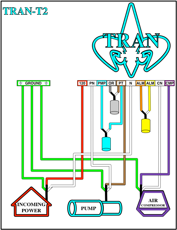
Tran-T2 Aerobic Septic Control Panel With Timer - With ...

Working model of septic pump and alarm system
0 Response to "38 septic pump wiring diagram"
Post a Comment