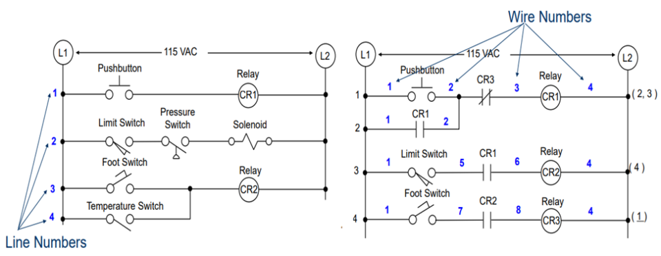
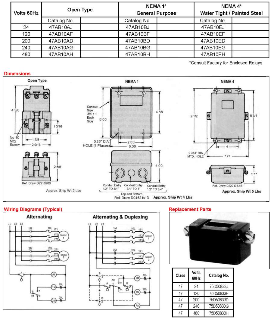
41 alternating relay wiring diagram
What Is The Difference Between Wiring Diagrams And ... A wiring diagram is a generalized pictorial representation of an electrical circuit. Like a block diagram a wiring diagram is a simplified graphical representation of an electrical circuit. The main difference between a wiring diagram and a block diagram is that wiring diagrams are mainly used in electrical applications. PDF 1-800-633-0405 r te latest rices lease cec AtmatinDirectcm ... Alternating Relays Wiring Diagrams AR-1C-120A-TL ARX-2C-120A-TL Alternating Relays Part Number Price Description Use With Drawing Links AR-1C-120A-TL $26.00 ProSense alternating relay, socket mount, finger-safe, 120 VAC coil voltage, SPDT, 10A contact rating, 8-pin, LED indicator(s). Relay becomes UL listed when used with 70169-D relay socket ...
Vw Beetle - Alternator Conversion Wiring Diagram - U Wiring Vw beetle - alternator conversion wiring diagram. 35 ECU Cloning - Reset To New Services Note. The alternator and generator wiring circuit works on a reverse live circuit. All the ecu programming tools available on the site are engineered intricately Oct 27 2020 ECU Flash tool is a free tool to upgrade the ECUS program memory firmware.

Alternating relay wiring diagram
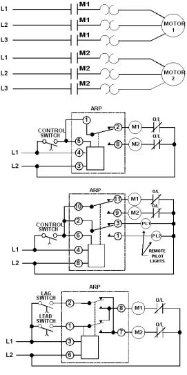
Typical Applications for Alternating Relays | Macromatic The Alternating Relay toggles to the LOAD 2 position. The entire cycle is then repeated, but with LOAD 2 energized first. Figure C. DPDT Cross-Wired. In the off state (Figure D), both the LEAD Switch and the LAG Switch are open, the Alternating Relay is in the LOAD 1 position, and both LOAD 1 & LOAD 2 are off. The red LED marked "LOAD 1" is ON. 44730 - Fuse Box And Wiring Diagram 44730 - 3 Pin Flasher, 6 Light Heavy-Duty Alternating Electronic within 3 Pin Flasher Relay Wiring Diagram by admin From the thousands of photos on the internet about 3 Pin Flasher Relay Wiring Diagram, selects the best choices along with greatest quality only for you, and this pictures is usually considered one of images libraries in this best images gallery concerning 3 Pin Flasher Relay ... PDF Wiring diagram for starter, alternator - DIY Sprinter Wiring diagram for starter, alternator Code: Designation: Coordinates: K57/4 48 A Battery cutoff relay RHD K88/1 9 L Body manufacturer tml. D+ relay K88/1 18 L Body manufacturer tml. D+ relay K88/1 28 L Body manufacturer tml. D+ relay K88/1 38 L Body manufacturer tml. D+ relay K88/1 50 L Body manufacturer tml. D+ relay N10 6 L SAM control unit ...
Alternating relay wiring diagram. CA2SKE20 - Alternating Relay Wiring - Scribd When the coil of the alternating relay is energized for the second time, the other contact will close and will open when the coil is de-energized. The control contacts (13-14 and 23-24) of the alternating relay are to be used in the control circuit of the starters which are controlling the pumps or compressor motors. Typical Wiring Diagram PDF Schneider Electric Alternating Relay To Match Wiring When Replacing A Hubbell Alternator (Which Uses a SPDT Contact Arrangement) Jumper Pins 13 & 23 On the Schneider Electric Alternator. SCHNEIDER ELECTRIC ALTERNATING RELAY *** When Selecting the Alternating Relay Choose the Model Number Closest to Your Operating Voltage. Coils Can Operate Within a 15% Range. ... Alternating Relay up to 4 loads: Function and Wiring Diagram AVAILABLE AT OUR ONLINE STORE: Alternating Relay is used in special applications where the optimization of ... 86 Mitsubishi l300 alternator wiring help? - Retro Rides What's the wire marked 2-W spured from the alternator cable? EDIT: just seen your post. That whole wiring diagram is a mess, I've never seen anything wired up like that before. Think I would run the headlight relay direct from the battery or a separate ignition relay, and make a new cable from battery to alternator.
Float Switch Installation Wiring & Control Diagrams | APG Let's start with the most basic float switch: a two-wire, single-pole, single-throw float switch.The rising action of the float can either close (i.e., turn on) a "Normally Open" circuit, or it can open (turn off) a "Normally Closed" circuit.Installation scenarios might include a Normally Open float switch turning on a pump to empty a tank (Control Schematic 2), or a Normally Closed ... Alternator Wiring Diagram: A Complete Tutorial | EdrawMax This is a three-wire alternating wiring diagram showing the connections between the different components of a circuit. The circuit comprises three main wires: battery positive cable, voltage sensing wire, and ignition wire. The ignition input wire is attached to the engine. It conducts electricity from the engine to the alternator while the ... D85 alternating relay instructions - Eaton Wiring Diagrams If the unit has the low-profile selector switch, set this switch to “ALTERNATE” for normal operation. In this mode, the unit will operate as a normal Alternating Relay, alternating between the two loads on each subsequent closing and opening of the control switch. Setting the selector switch to either “LOAD Automation Controls Catalog - crouzet-control.com WIRING DIAGRAM: ORDERING INFORMATION: The electronic alternating relay is designed to replace mechanical style devices used in control applications requiring a duplexing or alternating action of the control circuits to operate pumps, compressors, etc. This is achieved by activating a control switch
How To Wire Alternator - Vintage Auto Garage and connect the red wire to the output side of the alternator 10/32 stud, take the long wire and connect to the + side of the coil. If you are using a coil with external ballast resistor connect this wire to the battery side or key switch side of How To Wire Alternator 12-VOLT NEGATIVE GROUND 3 WIRE INSTRUCTIONS Simple alternator wiring diagram | Alternator, Car ... 35 Awesome ford Starter Relay Wiring Diagram- A run relay is used in the automotive industry to restrict and bend the flow of electricity to various electrical parts inside the automobile. They allow a little circuit to govern a future flow circuit using an electromagnet to govern the flow of electricity inside the circuit. DAYTON Alternating Relay, 120V AC, 10A @ 240V, 10A @ 28V ... Alternating Relays with DPDT cross-wired outputs are used in applications requiring both (a) the optimization of load usage by equalizing the run time of two loads and (b) additional capacity in case of excess load requirements. ... be used with only one input device—simply wiring the single input device where the "LEAD" input is shown on ... Relay and Relay Circuits Schematic Circuit Diagram The overcurrent relays connected to the three phase conductors only control one relay in one phase alternating current circuits and the three phase conductors control the normally closed contact in the control circuit. In the overcurrent relays, the current is set by the adjusting screw on the relay.
Duralast Dl7078 Wiring Diagram - schematron.org Follow Ford wiring diagrams for each. The alternator is a Duralast DL - the same one I have from my 67 LTD. The only.Duralast Or Interstate Car Battery 6 Volt Rv Batteries Wiring Rechargeable 12 Volt Battery And Charger 12 Volt Auto Battery Reads 10 98 Volts 24 Volt Li Ion Battery Pack Wiring Diagram 12 Volt Battery Explosion Duralast Or ...
WIRING DIAGRAMS - Pajero 4x4 Off-Road Club WIRING DIAGRAMS 1993 Mitsubishi Montero 1993 WIRING DIAGRAMS Mitsubishi Wiring Diagrams Mitsubishi; Montero IDENTIFICATION COMPONENT LOCATION MENU COMPONENT LOCATIONS TABLE Component Figure No. (Location) A/C COMPRESSOR RELAY ..... 5 (D-E 19) A/C ENGINE COOLANT TEMPERATURE SWITCH .....
Alternator Voltage Regulation 101 (with Wiring Diagrams ... Field or ignition terminal: Allows battery voltage from the ignition to flow to the alternator's field coil during startup. Electronic voltage regulators have been used on many cars since the mid 1970s. 3-Wire Alternator Wiring Diagram. Refer to the diagram below if you're working on three-wire connections.
December 2020, Rev D 901-0000-323 - Macromatic Alternating Relays December 2020, Rev D 901-0000-323 ... terminal numbers on the socket to the ones shown on the appropriate wiring diagram (the wiring diagram on the relay is the view looking towards the bottom of the relay vs. the top of the socket). Plug the relay into the socket, making sure the key on the center post is in the proper
Relay Wiring Diagram: A Complete Tutorial | EdrawMax The diagram above is the 5 pin relay wiring diagram. There are different kinds of relays for different purposes. It can be used for various switching. Relay can be the best option to control electrical devices automatically. 5 pin is compromised of 3 main pins and an SPDT (single pole double throw).
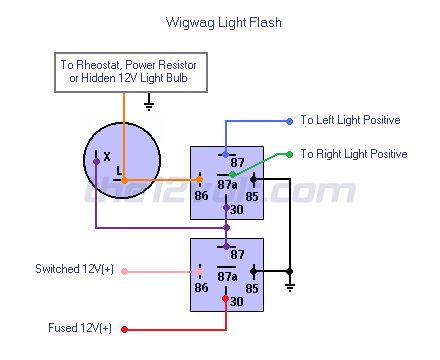
Wigwag Flashing Lights - Positive Input/Positive Output ... Wigwag Flashing Lights - Positive Input/Positive Output Relay Wiring Diagram. By placing a load on the flasher with a hidden 12V light bulb, power resistor or rheostat, the flasher will cause the coil of the top relay to energize and de-energize and in turn alternate 12V+ to each light for as long as terminal 86 of the bottom relay is connected ...
8 Pin Relay Wiring Diagram - Wiring Diagram 8 pin relay wiring diagram - You will want a comprehensive, professional, and easy to know Wiring Diagram. With such an illustrative guide, you'll be capable of troubleshoot, stop, and complete your tasks easily. Not merely will it help you attain your desired results quicker, but also make the complete procedure less difficult for everybody.
Time Mark 261 Series Alternating Relay Connect wiring to the socket as indicated in the following examples. The Model 261 series Alternating Relays are extremely versatile and can be used in many other configurations besides those shown. Any type of switch (float, pressure, etc.) can be used as the control switch; however, it must be connected as shown (from L1 to the
3 Pin Flasher Relay Wiring Diagram | Fuse Box And Wiring ... 3 Pin Flasher Relay Wiring Diagram - thanks for visiting my website, this blog post will certainly go over regarding 3 Pin Flasher Relay Wiring Diagram. We have collected many photos, with any luck this photo works for you, and help you in finding the answer you are looking for. Description : Flasher Units Norwood
PDF MODEL 261 series Alternating Relays - Allied Electronics Connect wiring to the socket as indicated in the following examples. 11 3 The Model 261 series Alternating Relays are extremely versatile and can be used in many other configurations besides those shown. Any type of switch (float, pressure, etc.) can be used as the control switch; however, it must be connected as shown (from L1 to the
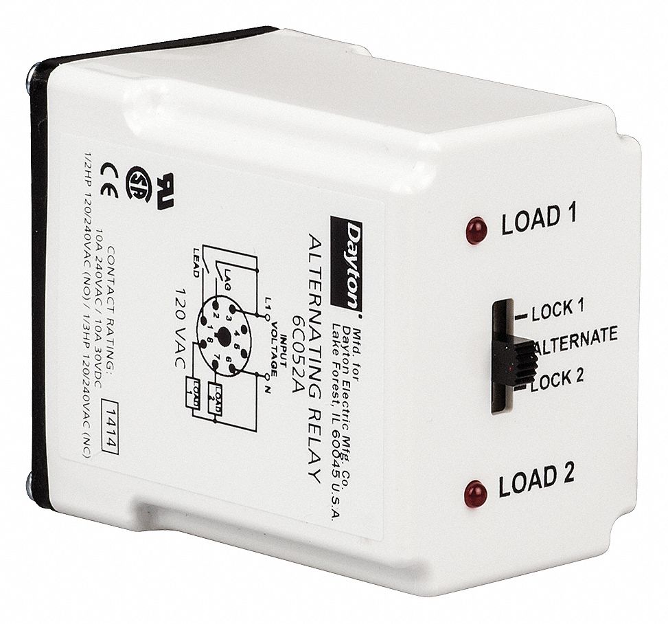
Alternating Relay, 240V AC, 10A @ 240V, 10A @ 28V, Octal Base Type, 8 Pins, 3.0 VA, DPDT Cross-Wired
Air Comp.Duplex W/Auto Alternation Diagram | Mike Holt's Forum I'm looking for a wiring diagram for an existing, old Furnace MCC with double throw single pole relay to alternate 2 air compressors. Each compressor has its own pressure switch, all the control circuit is fed from one source. The starters have 1 nc & 2 no aux contacts.
PDF Wiring diagram for starter, alternator - DIY Sprinter Wiring diagram for starter, alternator Code: Designation: Coordinates: K57/4 48 A Battery cutoff relay RHD K88/1 9 L Body manufacturer tml. D+ relay K88/1 18 L Body manufacturer tml. D+ relay K88/1 28 L Body manufacturer tml. D+ relay K88/1 38 L Body manufacturer tml. D+ relay K88/1 50 L Body manufacturer tml. D+ relay N10 6 L SAM control unit ...
44730 - Fuse Box And Wiring Diagram 44730 - 3 Pin Flasher, 6 Light Heavy-Duty Alternating Electronic within 3 Pin Flasher Relay Wiring Diagram by admin From the thousands of photos on the internet about 3 Pin Flasher Relay Wiring Diagram, selects the best choices along with greatest quality only for you, and this pictures is usually considered one of images libraries in this best images gallery concerning 3 Pin Flasher Relay ...
Typical Applications for Alternating Relays | Macromatic The Alternating Relay toggles to the LOAD 2 position. The entire cycle is then repeated, but with LOAD 2 energized first. Figure C. DPDT Cross-Wired. In the off state (Figure D), both the LEAD Switch and the LAG Switch are open, the Alternating Relay is in the LOAD 1 position, and both LOAD 1 & LOAD 2 are off. The red LED marked "LOAD 1" is ON.


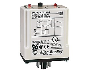


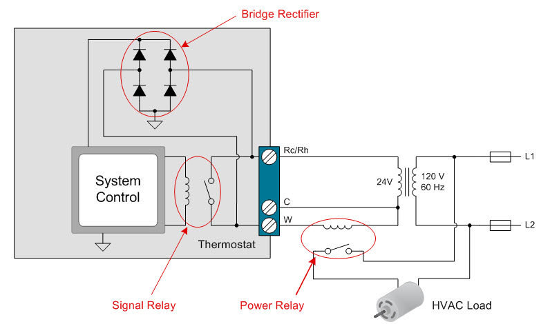
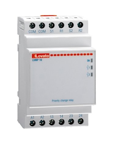










0 Response to "41 alternating relay wiring diagram"
Post a Comment