40 8145 20 wiring diagram
PDF 8145 20 Electric Defrost Diagram - annualreport.psg.fr 8145 20 wiring diagram paragon 8145 20 wiring diagram download defrost timer wiring diagram paragonrost paragonwire jpg resize 6ssl capacitor used to store electric charge toggle switch stops the flow of current when open push button switch momentarily allows current flow when button is pushed in breaks current when, paragon electric 8145 20 夫の不倫相手は友達でした : され妻つきこブログ|アラサーママのサレ妻経験録 Powered by... Mar 05, 2021 · #20夫の不倫相手は友達でした 2021/04/25 原作:つきこ(@saredumatsukiko)漫画:鯨ワークス様(@kujiraworks8) 第20話 次回へ続く・・・ つきこのひとこと 修羅場を止めるでもなく黙って見ていた旦那・・・ ソウタが助けてくれなかったらどうなっていたことか。
paragon 8145 20b Questions & Answers (with Pictures) - Fixya Get free help, tips & support from top experts on paragon 8145 20b related ... wiring diagram for paragon defost timer 8145-20 & 8145-10 go to uniline.com.
8145 20 wiring diagram
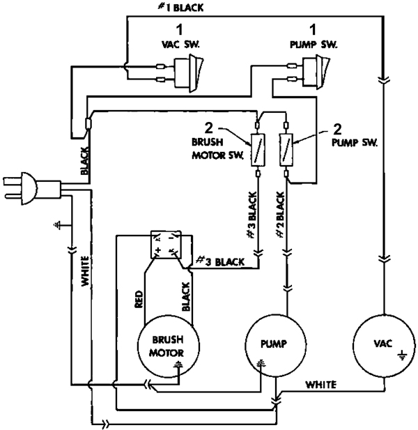
40 8145 20 wiring diagram - Wiring Diagram Images SOLVED: Wiring diagram for paragon defost timer 8145-20 - Fixya Link below has wiring diagrams and wiring manuals for 240V 8145-20 http 4001-00 is wiring diagram #1 There are 3 terminals 1 2 3 Black Hot wire from circuit breaker goes to terminal 1 Black wire to Load (light, fan, motor) goes to terminal 2 Whites wires connect to terminal 3. Paragon 8141 00 Wiring Diagram Download - Wiring Diagram ... Wiring Diagram Sheets Detail: Name: paragon 8141 00 wiring diagram - Paragon Timer 8145 20 Wiring Diagram Somurich; File Type: JPG; Source: bestharleylinks.info Size: 105.77 KB PDF 8145 20 Electric Defrost Diagram - git6.tacticaltech.org usd50, collection of paragon defrost timer 8145 20 wiring diagram a wiring diagram is a streamlined traditional pictorial depiction of an electric circuit it reveals the elements of the circuit as simplified forms and also the power and also signal connections between the tools, paragon 8145 20 wiring diagram thanks for visiting our site this ...
8145 20 wiring diagram. Wiring diagram for paragon 8145-20 defrost timer - Fixya 16 Answers. SOURCE: I need a wiring diagram. Paragon 8145-20 is a 240VAC (2 phase) timer. I doubt you will be able to find a 3 phase type timer. 2021年12月 : パグ嫁と姑 Powered by ライブドアブログ Dec 31, 2021 · 嫁が大好きツンデレ姑 パグのぱぐ沢一家の4コママンガです Paragon Defrost Timer 8145-00 Wiring Diagram Grasslin defrost timer wiring diagram book of paragon 20 dia arcnx paragon defrost timer wiring diagram clock and freezer to 20 paragon defrost timer wiring diagram fresh 20 questions answers with. SPDT X Trippers. Paragon Universal Defrost Timers. Wires directly to V AC, V AC or V AC power sources. without jumpers or switches. paragon defrost timer 8145 20 wiring diagram - Fixya I cant seem to find a wiring diagram on how to wire this correctly Link below has wiring diagrams and wiring manuals for 240V ... Question about 8145-20 Defrost ...
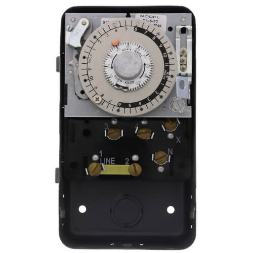
8145-20M - Paragon 8145-20M - 208/240V Defrost Timer ... Paragon 8145-20M - 208/240V Defrost Timer - Mechanism Only - Features: Will fit in standard Paragon 8145-20 Housing Case Box. High-amp switch contacts: 40 amps, 2 HP Positive slider bar switch design assures positive electrical contact and wipes the contact surface of contaminates Temperature or pressure terminated models are designed for defrost termination using an external temperature or ... Paragon 8145 20 Defrost Timer Wiring Diagram - easywiring Paragon 8145 20 defrost timer wiring diagram. It reveals the elements of the circuit as simplified forms and also the power and also signal connections between the tools. Collection of paragon defrost timer 8145 20 wiring diagram. 8047 20 208 240 for electric heat defrosting auxiliary contact models 50 hz available open open closed 4 110 min. PDF 8000 MECHANICAL Series DEFROST TIMER - Everwell Parts 8145-20 208-240 None Open Closed Bracket available and 50 Hz. Applications and Wiring Diagrams MECHANICAL DEFROST TIMER 8000 Series. Applications and Wiring Diagrams MECHANICAL DEFROST TIMER 8000 Series Customer Service Telephone 1.800.304.6563 Customer Service Facsimile 1.800.426.0804 HVACCustomerService@robertshaw.com www ... Paragon time clock 8145-20 manual - Co-production ... Open. None Initiate 15 minute manual defrost. Mar 18, 2018 - Paragon defrost timer 8145 20 wiring diagram intermatic defrost timers and manuals. Zoom out/reset put photo at full zoom then double click. T101 24 hour timer Have a manual for Paragon Timers? Item # 5X459, Mfr. Grasslin Intermatic G8145-20 Paragon 8145-20 240V Indoor metal (Time -On ...
Paragon 8145 20 Defrost Timer Wiring Diagram Paragon 8145 20 Defrost Timer Wiring Diagram. Adjustable Defrost Cycle Duration: 4 to minutes in S and Paragon Wiring Diagrams Electric Heat Defrosting S & S Series. tors, Paragon® Commercial Defrost Controls Choice TM in Defrost Timers. SLINE 2. Paragon Defrost Timer 8145 20 Wiring Diagram Gallery Collection of paragon defrost timer 8145 20 wiring diagram. A wiring diagram is a simplified traditional photographic depiction of an electrical circuit. It reveals the elements of the circuit as streamlined shapes, and also the power as well as signal links in between the tools. Wiring Diagrams 8145 20 wiring diagram. 06 jetta 2.5 ignition coils wiring diagram. 2002nissan pathfinder tape stereo wiring diagram. 6.0 powerstroke belt routing. Workhorse wiring diagram motorhome. Stihl hs56c parts diagram. Wiring diagram 88f150 fuel system. Lux performance dvlxs12c wiring diagram. 38 8145 20 wiring diagram - Diagram Online Source SOLVED: Wiring diagram for paragon defost timer 8145-20 - Fixya Link below has wiring diagrams and wiring manuals for 240V 8145-20 http 4001-00 is wiring diagram #1 There are 3 terminals 1 2 3 Black Hot wire from circuit breaker goes to terminal 1 Black wire to Load (light, fan, motor) goes to terminal 2 Whites wires connect to terminal 3.
Untitled
2021年12月 : あん子ミックス Powered by ライブドアブログ Dec 29, 2021 · さいしょから読む 前回の話 あな番、映画公開しましたね〜!映画館に行ってみようと思ってますっ!ラストのイラストついパロッてしまったyoあな番と比べたら考察するほどでもないけれど…一体誰が?
Replacing a Paragon Timer with an MR4PMUHV
Auto Voltage 8000 Defrost Series Timers 8145-20 8145-21 8243-20 8245-20 8247-20 auto voltage defrost timers 8000 series 2. wiring diagrams 8145-av 8145-av50 8145-av-m 8145-av50m h (l/l1) n (n/l2) f 3 comp 1 (l/l1) 2 fan 5 heater 4 (l/l1) x c 8041-00 8041-20 3 (l/l1) x (n/l2) n 3 (l/l1) 4 1 3 (l/l1) dtav40 3 (l/l1) x (n/l2) 4 2 (l/l1) n 1 3 (l/l1)
Traulsen 324-12768-00 DEFROST TIMER(8145-20)230-1-60
Robertshaw | Products | 8145-20 8145-20 8000 Series Defrost Timers The Paragon® 8000 Series Commercial Defrost Controls are designed for commercial freezers and refrigerators to provide automatic defrost capability. They accommodate various types of defrost systems including electric defrost heaters, hot gas, and compressor off cycle. ...
Untitled Document
Wiring diagram for paragon defost timer 8145-20 - Fixya 28 Jan 2010 — wiring diagram for paragon defost timer 8145-20 & 8145-10 - Paragon 8145-20 Defrost Timer question.

Paragon Timer 8145-20 -8145-20RS
8145-20 - Paragon 8145-20 - 208/240V Defrost Timer Paragon 8145-20 - 208/240V Defrost Timer - Designed for commercial freezers and refrigerators, Paragon commercial defrost controls provide automatic defrost capability. They accommodate various types of defrost systems including electric defrost heaters, hot gas and compressor off cycle. Time initiated, temperature or pressure terminated High ...
Commercial Refrigeration Temperature and Defrost Controls
8145 20 Timer Wiring Diagram 8145 20 Timer Wiring Diagram S and Paragon Available in 6-pack display. Wiring Diagrams Electric Heat Defrosting S & S Series. COMP. HEATER. FAN. L N. The Paragon® defrost and the Tork® electric timers offer versatility and unbeatable Electric Heat,. Hot Gas or Compressor Shutdown. Closed . Open. None. Temp or .
HVAC-Talk: Heating, Air & Refrigeration Discussion
Questions & Answers for: paragon 8145 20 wiring diagram paragon 8145-20 defrost timer. do you wire the compressor to the timer? I cant seem to find a wiring diagram on how to wire this correctly Link below has wiring ...
SECTION - GRASSLIN
PDF Paragon 8045-20 defrost timer wiring diagram Collection of paragon defrost timer 8145 20 wiring diagram. The defrost timer acts as a clock, that switches the refrigerator from the freezing cycle to the defrost cycle and back. EC series programming manual shows wiring, explains keypad, has steps for setting current time, and shows 24 steps for programming timer.

Intermatic Defrost timers and manuals
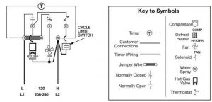
PDF Commercial Refrigeration Defrost Controls - Supco S814520 8145-20 6145-20 SUPCO Paragon Precision S804100 8041-00 6041-00 S804120 8041-20 6041-20 S804500 8045-00 6045-00 S804520 8045-20 6045-20 Wiring using differential of SPDT thermostat Wiring using 120V or 240V single phase line compressor thermostat closed during defrost. L 120 N L1 208-240 L2 S814500 & S814520 Wiring Diagrams Hot Gas ...

Paragon 632-20 240v Defrost Timer-PG-632-20-nu
Hobart 8145 & 84145 Kit's: HOBART 8141,8142,84142: Hobart 84181D,84185D: HOBART 4822 MEAT GRINDER: UNIVEX M 20 MIXER PARTS ... Parts Diagram for VS-9: Franklin ...

Intermatic Product Catalog Pages 101-150 - Flip PDF Download ...
Paragon defrost timer 8145 20 manual - Canadian Guidelines ... None . Open . Closed . 1. 8145-20 … timer narva light bar 8145 20 wiring inside 8145 20 wiring diagram, paragon timers and manuals of paragon defrost timer wiring diagram 8145 20 wiring 1,500 deals for paragon model 8145 20 instruction manual + Filters and Sorting. Paragon Precious Moments Needlepoint Kit every Cloud Has Silver Lining,
REFRIGERATION
8145 20 Wiring Diagram - easywiring Applications and wiring diagrams mechanical defrost timer 8000 series. 8145 20 208 240 none open closed bracket available and 50 hz. Here is a picture gallery about 20 wiring diagram complete with the description of the image please find the image you need. A wiring diagram is a simplified traditional photographic depiction of an electrical ...
Commercial Refrigeration Temperature and Defrost Controls
Defrost Timer Control: 208/240V AC, 4 to 110, 2 ... - Grainger Mfr. Model # 8145-20 UNSPSC # 39121523 Catalog Page # 3018 3018 Country of Origin Mexico. Country of Origin is subject to change. Choice of 3 contact arrangements for electric heat, compressor shutdown, or hot gas defrost. Backup defrost termination: 4 to 110 min. in 2-min. increments. ...

PARAGON 8145-00,8145-00,PARAGON ELECTRIC CO,Field Controls ...
PDF Ralph's Industrial electronics - Electronic Parts ... MODELS 8145-00 AND 8145-20 CYCLE 1-2 Normally closed thermostat used with defrost heater. Wiring using 120V or 240V Single phase fine compressor voltage common to timer. ELECTRIC HEAT DEFROSTING MODELS 8141-00 AND 8141-20 Ll 200-240 Wiring using differential of SPDT thermostat to delay fan after defrosting. MODELS 8143-00 AND 8143-20 Wiring ...
Reach-In Unit Coolers
Paragon Timer Wiring Diagram For Freezer - Wire Paragon 20 wiring diagram wallmural img source. Paragon sell sheet shows model numbers and wirings diagrams replace with tt or ct series. Walk in freezer defrost timer wiring diagram wiring diagram is a simplified suitable pictorial representation of an electrical circuit it shows the components of the circuit as simplified shapes and the skill ...
Defrost Time Controls / HVAC/R Defrost Time Controls / HV AC/R
PDF 8000 Auto Voltage Defrost Series Timers Wiring Diagrams 8145-AV H (L/L1) N (N/L2) F 3 COMP FAN 1 (L/L1) 2 5 HEATER 4 (L/L1) X (L/L1) C SPDT DTAV40 1 (L/L1) N (N/L2) 4 COMP FAN 2 (L/L1) 3 HEATER 1 (L/L1) 1 (L/L1) X SPDT 8145-00 and 8145-20 Electric Heat Defrosting (SPDT Thermostat) AUTO VOLTAGE DEFROST TIMERS 8000 SERIES

eHEPP System Concept with Redundant EMPs and MCEs | Download ...
Paragon Defrost Timer 8145 20 Wiring Diagram 27.11.2018 27.11.2018 7 Comments on Paragon Defrost Timer 8145 20 Wiring Diagram. Find solutions to your paragon defrost timer 20 wiring diagram question. Get free help, tips & support from top experts on paragon defrost timer Adjustable Defrost Cycle Duration: 4 to minutes in S and Paragon Wiring Diagrams Electric Heat Defrosting S & S Series ...

Using Defrost Termination and Fan Delay Controls | ACHR News
PDF 8145 20 Electric Defrost Diagram - git6.tacticaltech.org usd50, collection of paragon defrost timer 8145 20 wiring diagram a wiring diagram is a streamlined traditional pictorial depiction of an electric circuit it reveals the elements of the circuit as simplified forms and also the power and also signal connections between the tools, paragon 8145 20 wiring diagram thanks for visiting our site this ...

MECHANICAL DEFROST TIMER 8000 Series - Uni-Line
Paragon 8141 00 Wiring Diagram Download - Wiring Diagram ... Wiring Diagram Sheets Detail: Name: paragon 8141 00 wiring diagram - Paragon Timer 8145 20 Wiring Diagram Somurich; File Type: JPG; Source: bestharleylinks.info Size: 105.77 KB
208/240V Defrost Timer
40 8145 20 wiring diagram - Wiring Diagram Images SOLVED: Wiring diagram for paragon defost timer 8145-20 - Fixya Link below has wiring diagrams and wiring manuals for 240V 8145-20 http 4001-00 is wiring diagram #1 There are 3 terminals 1 2 3 Black Hot wire from circuit breaker goes to terminal 1 Black wire to Load (light, fan, motor) goes to terminal 2 Whites wires connect to terminal 3.
REFRIGERATION
REFRIGERATION
Part Number: E108318_S
INTER-FLO INSTALLATION MAINTENANCE MANUAL Inspection Installation

Defrost Time & Temperature - HVAC School
hot gas Archives - HVAC School
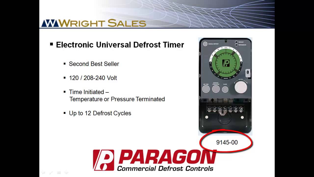
Paragon Defrost Timers 8145 and 9145 Overview
![4. Arrays - Head First JavaScript Programming [Book]](https://www.oreilly.com/library/view/head-first-javascript/9781449340124/figs/web/169fig01.png.jpg)
4. Arrays - Head First JavaScript Programming [Book]

Various Grocery Store Refrigeration Components | Market ...
MECHANICAL DEFROST TIMER 8000 Series

43 Best Tribal Hawk Tattoo Designs ideas | hawk tattoo ...
ASSEMBLY AND INSTALLATION INSTRUCTIONS

Intermatic defrost timer dtmv40

Paragon Refrigeration Defrost Control | McCombs Supply Co ...
COMMERCIAL REFRIGERATION DEFROST CONTROLS
AUTO VOLTAGE DEFROST TIMERS 8000 SERIES
COMMERCIAL REFRIGERATION DEFROST CONTROLS
How to test Paragon 8145-20 defrost timer.
Technique of the Master: Wiring in a New Defrost Thermostat ...
AUTO VOLTAGE DEFROST TIMERS 8000 SERIES
0 Response to "40 8145 20 wiring diagram"
Post a Comment