39 working of metal detector with circuit diagram
Simple Metal Detector Circuit. A simple metal detector can be designed using proximity sensor, buzzer, and LC circuit (inductor connected in parallel with capacitor), which are connected as shown in the above circuit diagram. This circuit will make the LED to glow and buzzer to sound whenever it detects metal objects or targets. Instrumentation amplifier is a kind of differential amplifier with additional input buffer stages. The... The circuit diagram of a typical instrumentation amplifier using opamp is shown below. A circuit providing an... A high gain accuracy can be achieved by using precision metal film resistors for all the resistances. Because...
Sep 20, 2017 - Read this post to get good idea about circuit diagram of metal detector. Metal detector is used to check the persons in shopping malls, hotels, etc.

Working of metal detector with circuit diagram
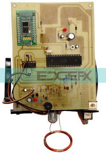
Metal Detector Circuit Diagram and Working. Read this post to get good idea about circuit diagram of metal detector. Metal detector is used to check the persons in shopping malls, hotels, etc. Mustapha Kamel Mfarredj. electronique. Electronics Mini Projects. Electronics Basics. HOW TO DIY ONE OF THE BEST METAL DETECTOR CIRCUITS is a premium Interactive video Tutorial. See bottom of Description for The Gold, Coins And Treasure Ebook.... The receiver circuit receives these commands through RF and moves the robot according to the received commands. A metal detector is interfaced to the controller in the receiver side. Thus whenever any metal is detected the robot stops there and buzzer starts ringing. Wireless Metal Detector Robot Circuit Diagram: Transmitter Circuit:
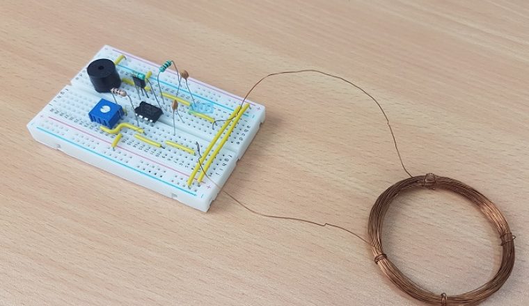
Working of metal detector with circuit diagram. Circuit Working of Peak detector. The figure below shows the circuit of a basic positive peak detector-It consists of a diode and capacitor along with an op-amp as shown above. The circuit does not require any complex component in order to determine the peak of the input waveform. Working Principle Metal Detector Circuit Diagram and Working In our daily life, we have got used to witness many detectors that detect metallic devices like guns, bombs, etc. To prevent any unlawful entry of guns and bombs in public places, a security system is developed by designing various electronics projects by using a proximity sensor. do not expect this metal detector to work like commercial metal detectors. You could make Metal Detectors with complicated circuits to perfectly accomplish the job. But that is not point of this build, in fact the main point of the build is to familiarize with the basics of simple electronics. With the development of lidar technologies, the relevant algorithms of atmospheric feature layer detection have also been continually proposed and improved. Aforetime, the cloud boundary was determined only relying on the difference between scattering from atmospheric particle layers and the background molecules [] or slope of...
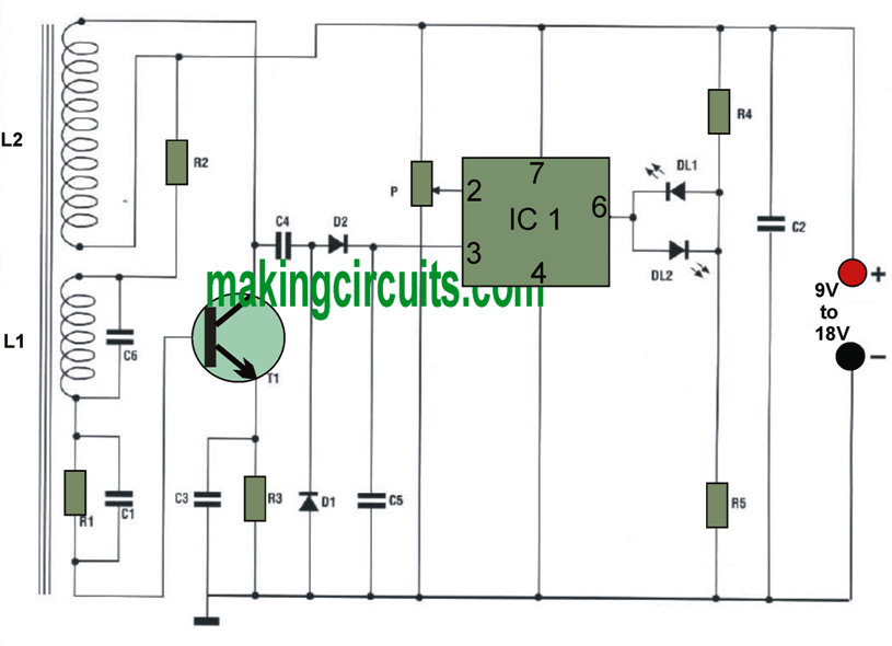
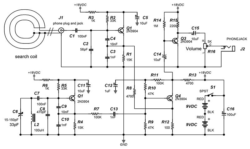
Metal Detection Design There are multiple variations of Metal Detector designs. This particular type of metal detector is a Pulse Induction detector which uses... With no objects in range, the baseline pulse width measures approximately 5000 uS. When foreign metal objects come into range of the expanding and collapsing magnetic... For this metal detector project, we will be using an Arduino to process the oscillation signal instead of offsetting the oscillation with a second tank circuit. The Arduino will store the fixed frequency and continuously compare the incoming frequency of the detector circuit with the stored frequency (more on the Arduino program below). 4 x 1 mm • Fast, accurate distance ranging – Histogram based technology – Up to 300 cm+ detection with full field of view (FoV) – Immune to cover glass... 2 System block diagram Figure 1. VL53L3CX block diagram VL53L3CX module VL53L3CX silicon Single Photon Avalanche Diode (SPAD) Detection array Non Volatile Memory ROM... Feb 3, 2020 — How does it work? · Electric schematic · The search coil (L1) · The fixed coil (L2) · Components · Oscillations · The mechanical parts · You can build ...
Using photons affords the advantage of relatively non-invasive interaction with the biological system under study. In such techniques, the solid-state interface to the biological system is usually a complementary metal-oxide-semiconductor (CMOS) or charge-coupled device imager. The use of such wide-field imagers allows... DIY Metal detector project with PIC12F1572 (or PIC12F1840) microcontroller. This is open hardware DIY project. It is possible to make either pinpointer or a full size metal detector based on this circuit. Ported to the PIC12F1572 at 6.08.2107. PIC12F1840 still usable also. Figure 1. This is the circuit: Features: Very easy to build. Jun 2, 2020 — Working of the circuit:- how does metal detector work: 1.] The oscillator circuit is provided dc source so that it can generate alternating ... Simple Metal Detector Circuit Diagram and Working 1. Simple Metal Detector Circuit Diagram and Working 2. http://www.elprocus.com/ Introduction To prevent any unlawful entry of guns and bombs in public places, a security system is developed by designing various electronics projects by using a proximity sensor.
Metal Detectors Circuit and Working – iMaxGeek
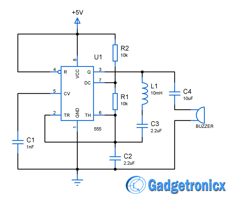
May 14, 2015 · Metal Detector Circuit Diagram and Working. The figure shows the circuit diagram of metal detector . The 555 IC timer here acts as a square wave generator and it generate pulses with frequencies audible to human. The capacitor between pin2 and pin1 should not be changed as it is need to generate audible frequencies.
BASIC CIRCUITRY of Metal Detection
This circuit is under:, sens detectors, metal detector circuits, Beat Balance Metal Detector l7119 Various embodiments of the BB metal detector have been published, and it has been widely described in the press as a new genre. Instead of using a search and a reference oscillator as with BFO, or Tx

Metal Detector Circuit Diagram Free Download Image Search ...
Metal detector The operation of metal detectors is based upon the principles of electromagnetic induction. The single-coil detector is the one used in a real metal detector. A pulsing current is applied to the coil, which then induces a magnetic field. When the magnetic field of the coil moves across metal, such as the coin, the field induces ...
Metal sensor
Simple Metal Detector Circuit Diagram and Working Metal Detector The first industrial metal detector was developed in the year 1960 A metal detector is an electronic device. An oscillator which ...

Ultra Sensitive Metal Detector
Simple Metal Detector: The other day when I was searching instructables I come across on interesting and simple circuit for metal detector. It is build with 555, coil and few other components. Instructable that inspire me to do this project was this one. Main debate was: …

Simple Metal Detector Circuit - Electronics Projects
It has only been with the aid of recently developed polarisation imaging technologies (e.g. Powell and Gruev; Roberts et al.; York et al.; Gagnon and Marshall) that we are beginning to uncover the complexities of the polarisation patterns that exist in nature and, with this, starting to understand how animals use this...

Cheap Metal Detector Circuit
In order to ensure safe operation, all electrical equipment must be installed and maintained in accordance with the provisions of the National Electrical Code (NEC) of the National Fire Protection Association (NFPA, 1991a). Laboratory workers should also consult state and local codes and regulations, which may contain special...
Metal detector circuit using IC 555 - Gadgetronicx
CircuitsTune.com provides a huge collection of electronics circuit diagram,wiring,schematic diagram and PCB layout of inverter,amplifier,power supply etc

Basics of metal detectors
Metal Detector Kasper Jensen C:\Documents and Settings\KJ\My Documents\Metaldetector.doc 6 01 December Active detectors uses the coil to transmit a pulse or a continually waveform, some uses the same coil to receive with, and others have 1 or 2 receiving coils.

metal detector robot using pic microcontroller
range of fields. A superconducting nanowire single-photon detector (SSPD or SNSPD) is one of the best... measured with an SFQ signal processor. In this paper, we report the full operation of the 4 × 4-pixel SSPD array system in a 0.1 W Gifford–McMahon (GM) cryocooler system.Figure shows a conceptual circuit diagram of...

Pulse Induction Metal Detector - Rx Methods - Project ...
electronic metal detector circuit, see Fig. 2, uses a Hall Effect sensor to detect weak permanent magnetic fields. Almost all ferrous objects retain some degree of magnetism, and those that do are easily detected with... Here is a simple diagram showing the typical inductor needed for metal-detector circuits. ...

Metal Detector Circuit | IndianEngineer
Working of the Circuit. Upload the code to Arduino UNO and Power on the system. The Arduino asks us to place our finger in the sensor and press the switch. Place any finger (except the Thumb) in the sensor clip and push the switch (button). Based on the data from the sensor, Arduino calculates the heart rate and displays the heartbeat in bpm.
Metal Detector Circuit Diagram and Working
Jan 3, 2022 - Read this post to get good idea about circuit diagram of metal detector. Metal detector is used to check the persons in shopping malls, hotels, etc.
Metal Detector - Electronics Maker
A subwavelength-diameter tapered optical fiber coated with gelatin layer for fast relative humidity (RH) sensing is reported. The sensing element is composed of a... The gelatin coated taper shows smooth surface and uniform diameter (see inset of).Schematic diagram of a single-mode tapered fiber for RH sensing.Calculated...
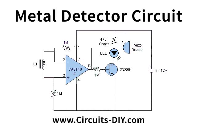
Simple Metal Detector using CA3140 IC
With 2 Ω circuit resistance and the minimum voltage of 9 Volt, the current over the coil will reach about 3.2 Ampere in the 250µsec mentioned above, which is more than adequate for a general purpose pulse induction metal detector with deep seeking capabilities.
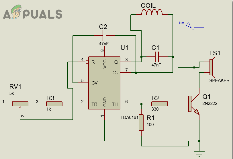
How To Make A Metal Detector Circuit? - Appuals.com
Metal detector circuit diagrams and projects Note that all these links are external and we cannot provide support on the circuits or offer any guarantees to their accuracy. Some circuits would be illegal to operate in most countries and others are dangerous to construct and should not be attempted by the inexperienced.
Metal Detector Circuit with Diagram and Schematic
Electronic valley in two-dimensional transition-metal dichalcogenides (2D TMDCs) offers a new degree of freedom for information storage and processing. The valley pseudospin can be optically encoded by photons with specific helicity, enabling the construction of electronic information devices with both high performance and low...
Simple Metal Detector Circuit with Applications
A DIY type Simple Metal Detector Circuit with easy construction and minimum components - Circuit Diagram, Components Required, Working Principle of the Proje...
Simple Metal Detector Circuit
top of light emitters. Importantly, the microlenses we propose readily form the collected light into an ultra-low divergence beam (half-angle divergence below 1°) perfectly suited for ultra-long-working-distance optical measurements (600 mm with a 1-inch collection lens), which are not accessible to date with other...

Simple Metal Detector Module
This circuit is under:, sens detectors, metal detector circuits, Beat Balance Metal Detector l7119 Various embodiments of the BB metal detector have been published, and it has been widely described in the press as a new genre. Instead of using a search and a reference oscillator as with BFO, or Tx
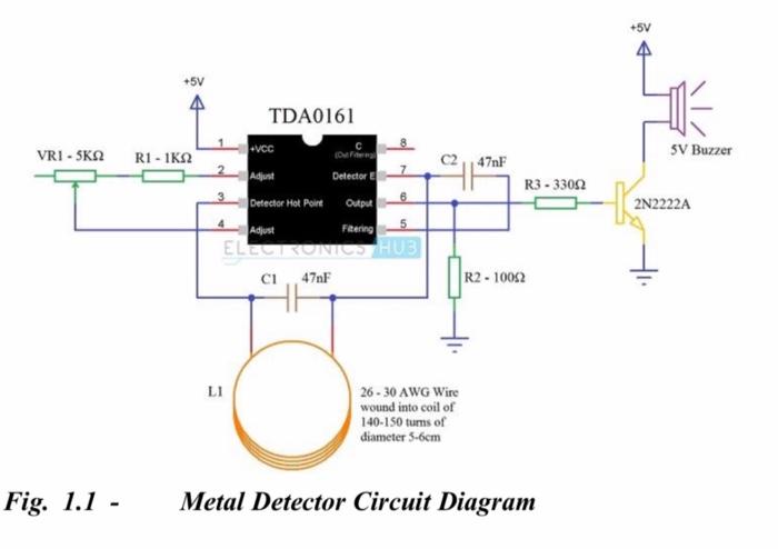
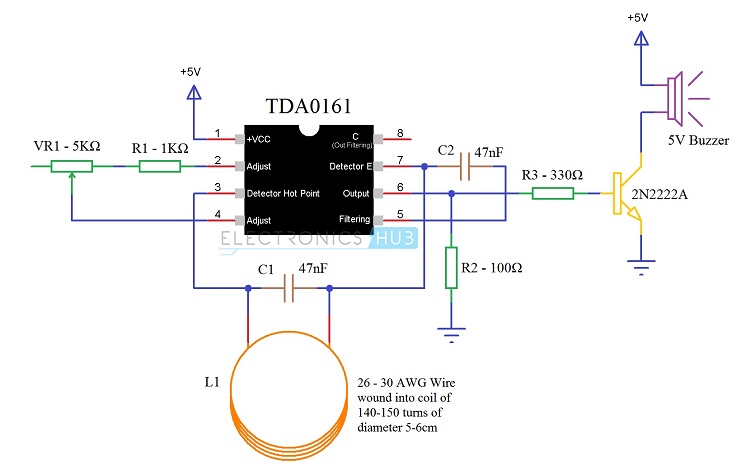
Solved +5V Ñ VRI - SKΩ R1 - 1K22 SV Buzzer 13 47nF R3 - 3300 ...
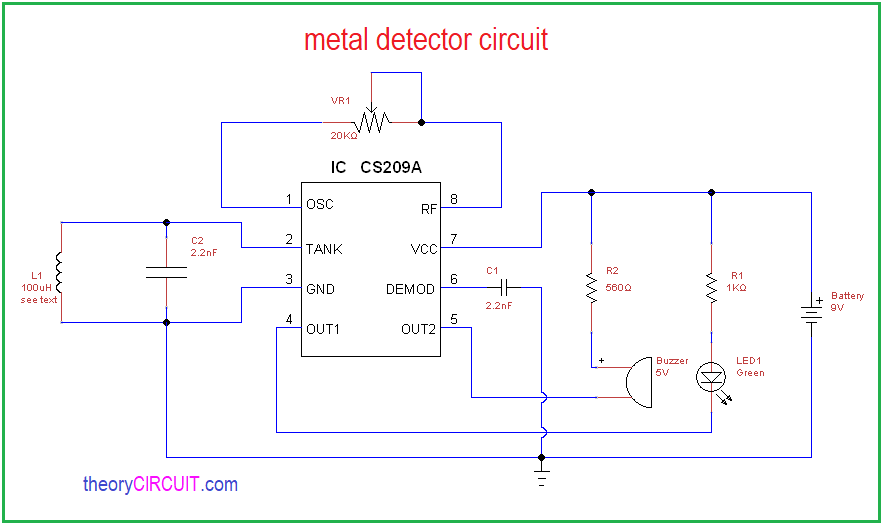
Metal Detector DIY Circuit. The heart of this diy metal detector circuit is the CS209A IC. The metal detector is built with one 100µH coil that has 40 mm in diameter and is made of 50 turns/0.4 mm wire. CS209A has one oscillator wich forms a LC circuit, the inductance of the coil will change when it is near metal objects.
How To Make A Metal Detector Circuit? - Appuals.com
Dec 05, 2018 · Circuit Diagram. Construction & Working. Important part in this circuit is designing the Inductor coil L1, because the sensitivity and output result are based on this Inductor only, here L1 value obtained to 100μH using Insulated copper coil 0.4mm wire, the L1 has 40mm in diameter and made of 50 turns.

Metal Detector Circuit | Circuit Diagram
This circuit is under:, sens detectors, metal detector circuits, Beat Balance Metal Detector l7119 Various embodiments of the BB metal detector have been published, and it has been widely described in the press as a new genre. Instead of using a search and a reference oscillator as with BFO, or Tx
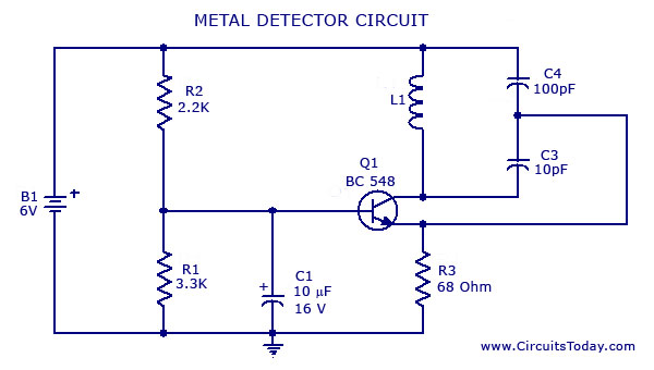
Metal Detector Circuit Diagram and Working
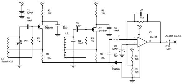
Signal Detector while Transistor part of the circuit act as the indicator. The capacitors collection along with the antenna are used to detect RF Signals when a... Schottky diodes are special diodes formed by combining N type semiconductor material with a metal and are typically low noise diodes, operating at a high frequency....
Find Concealed Metal Pipes, Nails, Studs using this Circuit
Description. This is the circuit diagram of a low cost metal detector using a single transistor circuit and an old pocket radio. This is nothing but a Colpitts oscillator working in the medium band frequency and a radio tuned to the same frequency. First, the radio and the circuit are placed close.
Principles Of A Metal Detector: How To Make One Yourself ...
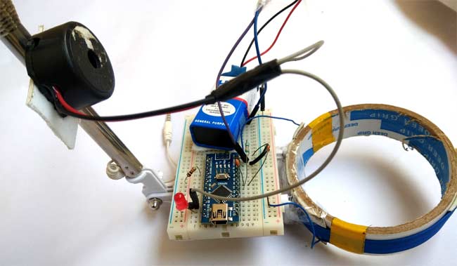
Circuit Diagram: We have used an Arduino Nano for controlling whole this Metal Detector Project. A LED and Buzzer are used as metal detection indicator. A Coil and capacitor is used for the detection of metals. A signal diode is also used for reducing the voltage. And a resistor for limiting the current to the Arduino pin.
Metal Detector Circuit Diagram and Working
How Metal Detector Works A pulsing current is applied to the coil, which then induces a magnetic field shown in blue. When the magnetic field of the coil moves across metal, such as the coin in this illustration, the field induces electric currents (called eddy currents) in the coin.
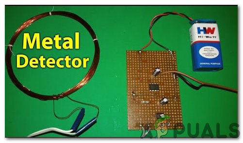
How To Make A Metal Detector Circuit? - Appuals.com
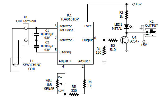
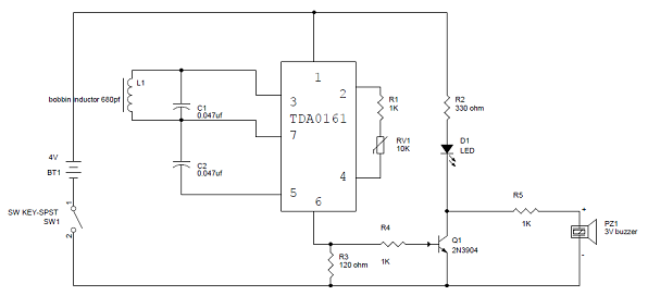
Jul 31, 2017 · The LC Circuit, which consists of L1 (coil) and C1, is the main metal detector part of the circuit. With the help of this LC Circuit, which is also called as Tank Circuit or Tuned Circuit, the TDA0161 IC acts as an oscillator and oscillates at a particular frequency.
Metal Detector Circuit
A block diagram of the circuit can be seen in Figure 2. Figure 2 – Block Diagram of the Pulse 1 Metal Detector The basic design of the metal detector consists of four parts as seen above. These are: • The power supply (four IC’s), • The pulse generation circuit (four 555’s, and coil),

Simple Metal Detector Circuit Using BC548 Transistor
A Li metal battery (LMB) using the FMF/Li electrode and a LiFePO 4 electrode exhibited a two-fold increase in cycling stability compared with that of a bare Li metal electrode, demonstrating the practical effectiveness of this approach for high performance LMBs.
Build Your Own Metal Detector with an Arduino - Projects
The receiver circuit receives these commands through RF and moves the robot according to the received commands. A metal detector is interfaced to the controller in the receiver side. Thus whenever any metal is detected the robot stops there and buzzer starts ringing. Wireless Metal Detector Robot Circuit Diagram: Transmitter Circuit:
Metal Detector Circuit | LaptrinhX
HOW TO DIY ONE OF THE BEST METAL DETECTOR CIRCUITS is a premium Interactive video Tutorial. See bottom of Description for The Gold, Coins And Treasure Ebook....

Circuit Design for Metal detector - EeeStudy
Metal Detector Circuit Diagram and Working. Read this post to get good idea about circuit diagram of metal detector. Metal detector is used to check the persons in shopping malls, hotels, etc. Mustapha Kamel Mfarredj. electronique. Electronics Mini Projects. Electronics Basics.

Intermediate Electronics Project #8 - METAL DETECTOR

How To Make a Metal Detector Circuit – Srelectrics.Com
Metal detector circuit using IC 555 and Buzzer - Gadgetronicx
Arduino Metal Detector Project with Code and Circuit Diagram
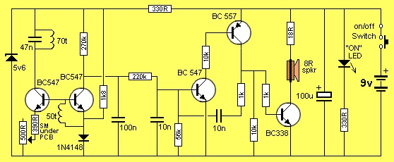
Build A Four Transistor Metal Detector | Nuts & Volts Magazine

Simple-Metal-Detector - Gold Detectors 2021 | Latest ...
0 Response to "39 working of metal detector with circuit diagram"
Post a Comment