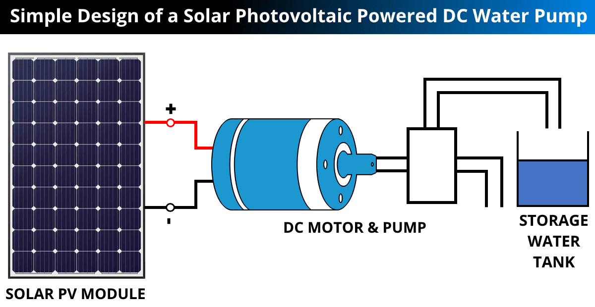
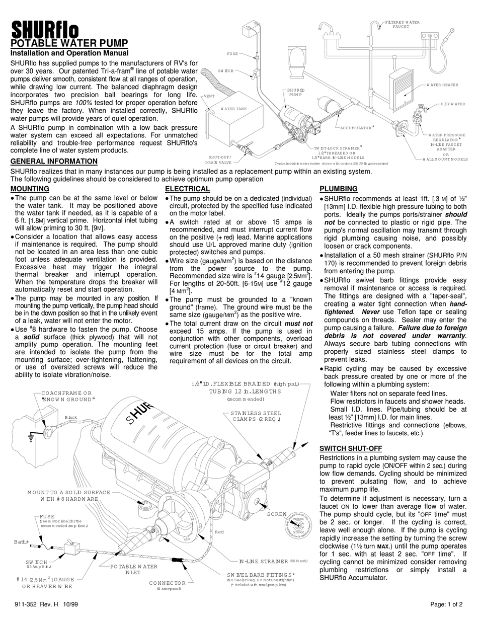
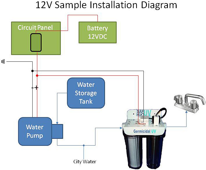
37 water pump installation diagram
Keywards:toilet repairplumbing servicesemergency plumberdrain cleanerlocal plumberswater heater installationplumbing companiesplumbers near meclogged drainbl... Jet Pump. Centrifugal Pump. Drain Pump. Oil And Gas. Diagram. Wellness. Infographics: Single Stage Deepwell Cargo Pump. Deepwell cargo pumps are electrically driven cargo discharge pumps which are now used in place of Cargo Operated Pump Turbine (COPT) on tanker ships. Learn about the different parts of the pump in this infographics.
Before Installation. Well pump installation can be dangerous when dealing with water and electricity, so extreme caution must be taken. Before getting started, look up your owner's manual and read over the precautions and all other warnings before beginning the installation. The manual will contain important safety precautions, wiring diagrams, tools required for assembly, proper grounding ...

Water pump installation diagram
250+ feet Call pump hotline: 1-888-956-0000 "Pumping water level" is the depth to the water while the well is being pumped. It is usually deeper than the depth to the water when the pump is not running. For a lake or cistern installation, it is the depth to the surface of the water. Jul 28, 2015 — How to install a water pump professionally? Which tools you will require to fulfill this task? To know the answers about these queries, ... Float Switch Connection Single Phase Water Pumpwhat is float switch?float switch is a type of level sensor a device used to detect the level of liquid within...
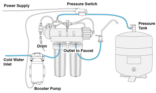
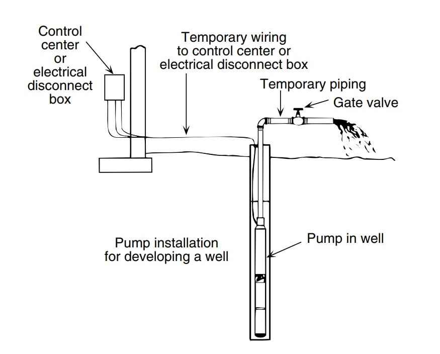
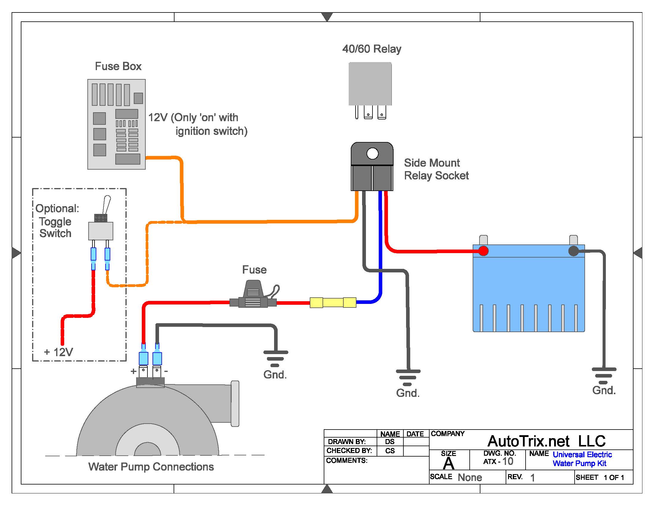
Water pump installation diagram. Electric Water Pump Installation Guide (Continued) Page 2 FORD SB(260-351W, 351C-400M, BB 429-460 ONLY: Using the gasket, 5/16" fasteners, and cover plate provided, apply sealant to the gasket and hand-tighten in place with the additional fasteners provided. The last four (4) fasteners will be used to secure the water pump to Apr 04, 2017 · So the complete Typical Pump Installation Setup For A Centrifugal Pump is shown in the below schematic: The flow to this Centrifugal Pump goes from Tank → Suction Gate Valve → Pipe Diameter Reducer → Pump Suction/Pump Discharge → Pipe Diameter Expansion → Check Valve → Discharge Gate Valve → Distribution Header Pipe. Booster Pump Installation Instructions 1. Install pressure switch in tank line. (See diagram on back for where to place the pressure switch). 2. Pump must be located within 2 feet of pressure switch and within 6 feet of power outlet. A. Pump can be mounted to the wall horizontally in either direction or vertically only one way ~ with pump head and your local electrical and pump professionals. 2. Install tank as close as possible to the pump pressure switch to reduce friction loss and elevation difference between the tank, water supply main, and switch. 3. After installation, be sure the pressure switch is set low enough to shut the pump off. If all valves are closed and the pressure switch
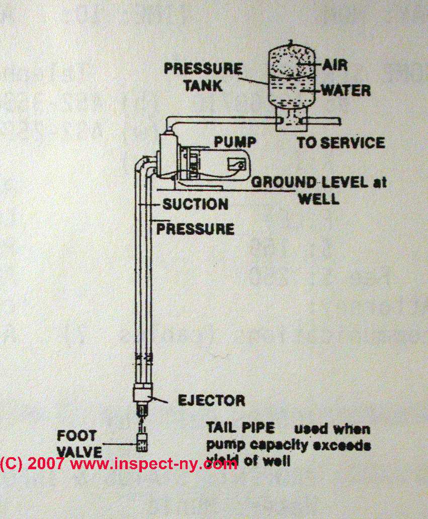
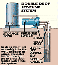
TYPICAL SHALLOW WELL JET PUMP INSTALLATION 1. Shallow well jet systems can be used when the depth of the water is no more than 20'. Water depths of more than 20' but less than 80' deep would use a deep well jet system or submersible pump. A submersible pump can also be used in shallow wells. 2. We recommend a captive air pump tank. SALT WATER SYSTEM INSTALLATION DIAGRAM 120/240 VAC POWER FILTER PUMP FROM POOL TIMER SOLAR SYSTEM SPA HEATER SALT SYSTEM CONTROL PANEL FLOW SWITCH TO SPA ELECTROLYTIC CELL IN-FLOOR CLEANER TO POOL . Title: Salt Water Pool Installation Diagram Author: Salt Water Pool and Spa Subject: Salt Water Pool Installation Diagram Keywords: salt water pool ... The water pump used in the hot water recirculating pump is ideally of a softball size. It is generally installed above the water heater or just below the sink. In most of the cases, installation above the heater has been rated to be one of the excellent options. Diagrams --Typical Pump Installations. The information provided here is for educational purposes only. Technically qualified personnel should install pumps and motors. We recommend that a licensed contractor install all new systems and replace existing pumps and motors. Failure to install in compliance with local and national codes and ...
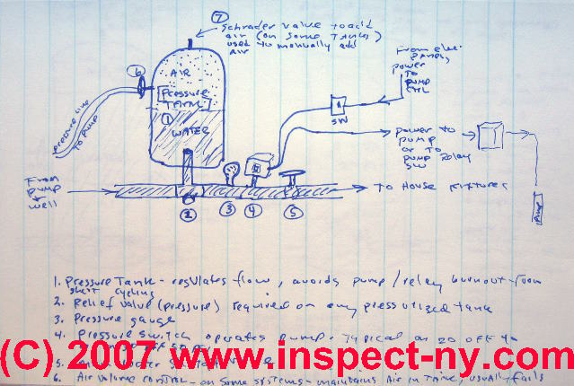
DIY installation of pressure pump. http://4pumps.com.au/pumps/pressure-pumps/ We're doing the plumbing on a new house and well, the water pump installation works which makes me very happy. It's good for heights up to 36M and my roof is... Install a one-way check valve in the feed line that goes to the pump. This will keep water in the shallow well pump and the plumbing system instead of going back down into the well. Run the shallow well pump and check several water samples before you use them. The water should be clean and free of silt, sand or other materials before you use it. Installed near the tank inlet to hold water in the tank during pump installation when the pump is idle. 8. Tank Tee Connets water line from pump to pressure tank and service line from tank to house. Taps are provided to accept Pressure Switch, Pressure Gauge, Drain Valve, Relief Valve, Sniffer Valve, etc. 9. Drain Valve Drain easy draining of ...
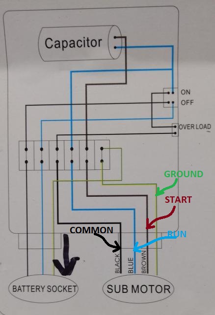
Single Phase Water Pump Installation DiagramTHANK`S FOR WATCHING THIS VIDEO PLEASE LIKE COMMENT SHARE AND SUBSCRIBE THIS CHANNLEhttps://www.youtube.com/chann...
Grundfos Home Water Booster Pump.⭐ Compare Our Price & Models Today!✓Grundfos Has Good Reviews & Best Reliability Quality. Low or shifting water pressure is ...
1 1/4” holes are full of water. STEP 5 Mount the pump onto the well adapter with gaskets and bolts, making sure that the 1 1/4” and 1” holes in pump line up with the holes in th e adapter. STEP 6 Prime the pump by pouring water into the discharge of the pump housing or automatic regulator mounted in discharge of the pump on some models.
Mount the valve under the sink and the pump at the water heater. The valve's unique thermal disk technology sends cooled water back to the water heater so hot water lines remain hot. Cleaning made easy. There's no need to remove the Hot-Link valve from the piping to keep it clean. Our exclusive clean-in-place design makes short
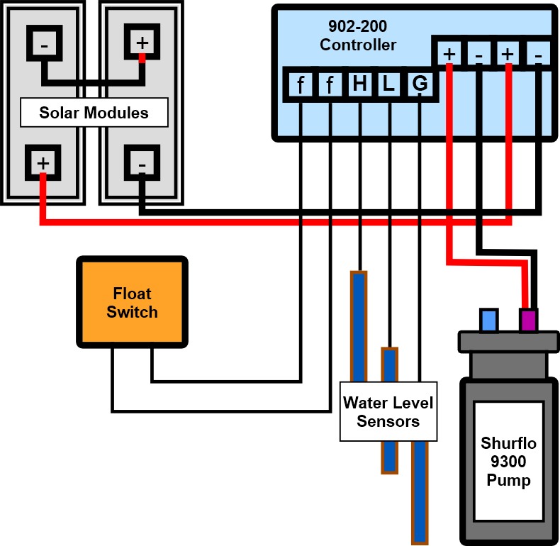
Submersible Pump Control Box Wiring Diagram For 3 Wire Single Phase Submersible Pump Submersible Electrical Circuit Diagram. Automatic Water Level Controller Wiring Diagram For 3 Phase Motor Submersible Pump Water Pump Motor Submersible Pump Electrical Installation. Booster Pump Explain New 2017 Youtube Well Pump Refrigeration And Air ...
Prevents surface water from seeping around casing into potable water. 11. Threaded and coupled galvanized pipe should be used on extremely deep wells. Threaded schedule 80 PVC and a heavy grade poly pipe are also available and are much lighter and easier to work with. 12. Position a torque arrestor directly above the top of the pump.
Float Switch Connection Single Phase Water Pumpwhat is float switch?float switch is a type of level sensor a device used to detect the level of liquid within...
Jul 28, 2015 — How to install a water pump professionally? Which tools you will require to fulfill this task? To know the answers about these queries, ...
250+ feet Call pump hotline: 1-888-956-0000 "Pumping water level" is the depth to the water while the well is being pumped. It is usually deeper than the depth to the water when the pump is not running. For a lake or cistern installation, it is the depth to the surface of the water.











0 Response to "37 water pump installation diagram"
Post a Comment