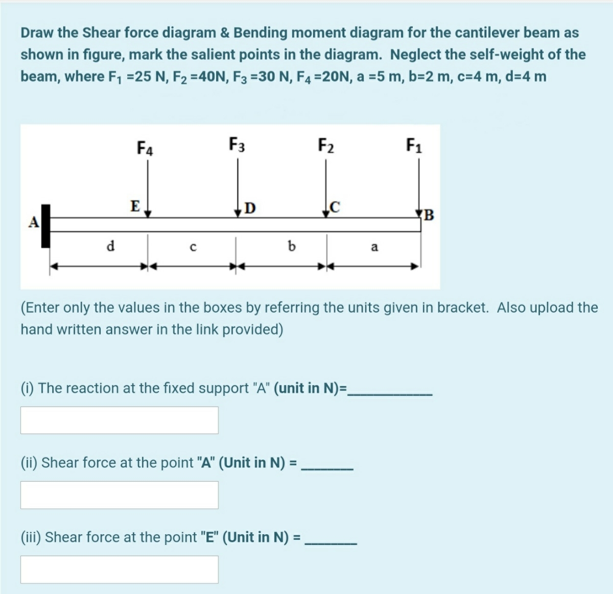
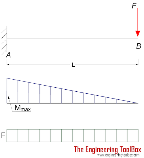
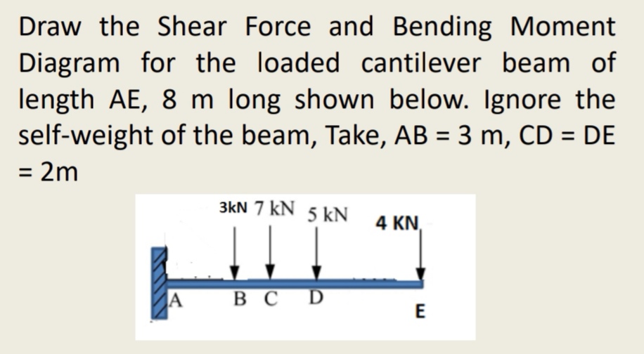
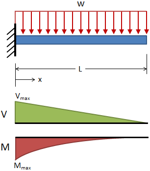
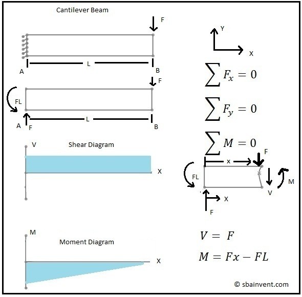
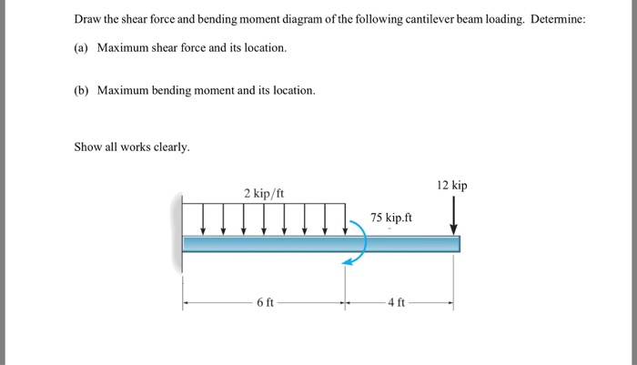
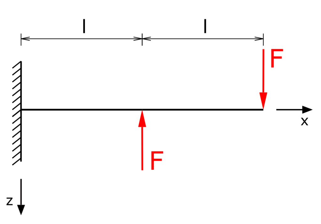
37 bending moment diagram cantilever beam
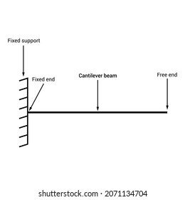
Cantilever – a projecting beam fixed only at one end. Trussed – a beam strengthened by adding a cable or rod to form a truss. Beam on spring supports; Beam on elastic foundation; Second moment of Area (Area moment of inertia) In the beam equation I is used to represent the second moment of area. It is commonly known as the moment of inertia, and is the sum, about the … 09.12.2021 · Bending Moment Equations for Beams. Bending Moment Equations and Formulas offer a quick and easy analysis to determine the maximum bending moment in a beam. Below is a concise table that shows the bending moment equations for different beam setups. Don’t want to hand calculate these, sign up for a free SkyCiv Account and get instant access to ...
accurate computation of the area of a moment diagram, as well as the moment of such area about any axis. To pave its way, this section will deal on how to draw moment diagrams by parts and to calculate the moment of such diagrams about a specified axis. 4.4.1 Basic Principles 1. The bending moment caused by all forces to the left or to the right of any section is equal to …

Bending moment diagram cantilever beam
The most common bending tests include cantilever, 3- and 4-point bending, and G-torsion as shown in Fig. 3.9. Fig. 3.9. Selection of the most common bending tests. (3.4) The stress for the simple linear elastic beam is calculated using: σ = Mc I where M: Bending moment about the neutral axis I: Moment of inertia about the neutral axis c: 1 / 2 depth c: radius, in the case of a … 16.10.2014 · Bending moment at point B = M(B) = R1 x Distance of R1 from point B. Bending moment at point B = M (B) = 1000 x 2 = 2000 kg.m. Bending Moment Diagram Simply Support Beam with UDL & Point Load Example. Draw shear force and bending moment diagram of simply supported beam carrying uniform distributed load and point loads. As shown in figure. … Figure 2 – Shear and Bending Moment Diagrams . 4 Using Design Aid Tables: Pu p M P L uu u u 33.6 8.33 280 kip-ft Figure 3 – Design Aid Tables (Beam Design Equations and Diagrams) – PCI Design Handbook 4. Flexural Design 4.1. Required and Provided Reinforcement For this beam, the moment at the fixed end governs the design as shown in the previous Figure. Mu t …
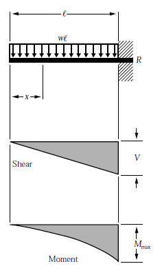
Bending moment diagram cantilever beam. A bending moment diagram is a diagram which shows the bending moment at every section of the beam due to transverse loading on it. In the case of a simply supported beam bending moment is zero at the ends, and for a cantilever, it is zero at the free end. For point loads, the B.M. diagram has straight inclined lines, for UDL, it has a parabolic curve and for the uniformly … 12.07.2021 · This cantilever beam deflection calculator is programmed to calculate the deflection profile, slope, shear force diagram (sfd), bending moment diagram (bmd) and end reactions. Required: Young’s Modulus (E) of the material, length (L) of the beam, area moment of inertia (I), load intensity (w1), distance at which w1 acts ‘a’, load intensity w2 and distance at which w2 … 11.11.2021 · Bending Moment Diagram Calculation. Below are simple instructions on how to calculate the bending moment diagram of a simply supported beam. Study this method as it is very versatile (and can be adapted to many different types of problems. The ability to calculate the moment of a beam is a very common practice for structural engineers and often ... Circular Cantilever Beam in Direct Tension and Bending Stress Equations and Calculator Circular Cantilever Beam in Direct Tension. For every calculated shear stress t here is a corresponding induced normal stress; the value of the normal stress …
Figure 2 – Shear and Bending Moment Diagrams . 4 Using Design Aid Tables: Pu p M P L uu u u 33.6 8.33 280 kip-ft Figure 3 – Design Aid Tables (Beam Design Equations and Diagrams) – PCI Design Handbook 4. Flexural Design 4.1. Required and Provided Reinforcement For this beam, the moment at the fixed end governs the design as shown in the previous Figure. Mu t … 16.10.2014 · Bending moment at point B = M(B) = R1 x Distance of R1 from point B. Bending moment at point B = M (B) = 1000 x 2 = 2000 kg.m. Bending Moment Diagram Simply Support Beam with UDL & Point Load Example. Draw shear force and bending moment diagram of simply supported beam carrying uniform distributed load and point loads. As shown in figure. … The most common bending tests include cantilever, 3- and 4-point bending, and G-torsion as shown in Fig. 3.9. Fig. 3.9. Selection of the most common bending tests. (3.4) The stress for the simple linear elastic beam is calculated using: σ = Mc I where M: Bending moment about the neutral axis I: Moment of inertia about the neutral axis c: 1 / 2 depth c: radius, in the case of a …









![[Ex. 07] Shear Moment Diagram Cantilever Beam Distributed Load Part I](https://i.ytimg.com/vi/qMk5IVKcZQM/maxresdefault.jpg)

0 Response to "37 bending moment diagram cantilever beam"
Post a Comment