42 d orbital splitting diagram
splitting in a magnetic field for the 2P 3>2, 2P 1>2, and 2S 1>2 energy levels for sodium, showing the anomalous Zeeman effect. These are the D 1 and D 2 lines in Figure 7-22. The splitting of the levels depends on L, S, and J, leading to more than the three lines seen in the normal effect. [Photo from H.E. White, Introduction to Atomic d-orbital diagram for [Fe(H 2 O) 6] 3+: The first three electrons go into t 2g orbitals unpaired. The 4th and 5th electrons must choose whether to pair up with electrons already in t 2g (which costs energy) or to go into higher energy e g orbitals (which also costs energy). In this case, the splitting energy is less than the pairing energy so the 4th and 5th electrons go into the e g orbitals.
The d orbital splitting diagram is shown in a box. Suppose the diagram above is for a first row transition metal. The diagram for a second or third row metal is similar, but with stronger bonds. If the bonding interaction is stronger between the metal and ligand, then so is the antibonding interaction. The antibonding levels are bumped higher ...

D orbital splitting diagram
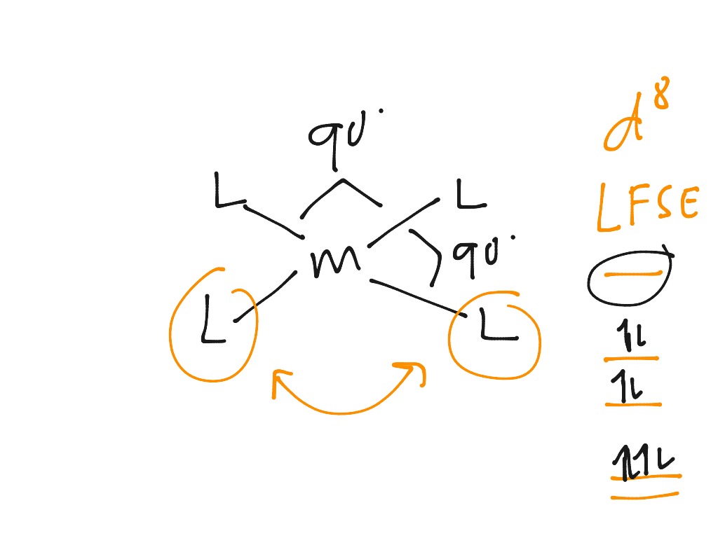
d) [Co(CN) 6] 3- (low spin) Hexacyanocobaltate(III) ion. The oxidation state of Co is 3+ so the electron configuration is d 6 (t 2g 6) so LFSE = -24Dq + 2P. e) [Ni(NH 3) 4 Cl 2] cis-Tetraamminedichloronickel(II) or trans-tetraamminedichloronickel(II) The oxidation state of Ni is 2+ so the electron configuration is d 8 (t 2g 6 e g 2) so ... Crystal Field Splitting (CFS) Diagram | Strong and Weak Field Ligand | d- orbital splitting - 9#ForAnyQuestion_9840225631#Class_11_12_BSC_Coordination_Compou... M2+ with 8 d electrons: M = Pt Pt Cl NH3 Cl NH3 10.4 Angular overlap calculations for d 8 and d 9 ions show no energy difference between D4h and Oh when exclusively considering interactions. Both d 8 geometries have energies of -3e ; both d 9 geometries have energies of -6e . In general, stability constants decrease as more
D orbital splitting diagram. Water splitting, which encompasses the hydrogen evolution reaction (HER) and the oxygen evolution reaction (OER), is a promising approach for large-scale and sustainable production of hydrogen (H 2) and oxygen (O 2).However, the water splitting kinetics is slow, and noble metal catalysts such as platinum (Pt), ruthenium (IV) oxide (RuO 2)/ iridium (IV) oxide (IrO 2) are … D-orbital splitting diagrams Use crystal field theory to generate splitting diagrams of the d-orbitals for metal complexes with the following coordination patterns: 1. Octahedral 2. Tetrahedral 3. Trigonal bipyramidal 4. Square pyramidal d z2x2-y d xy d yzxz 5. Square planar d z2x2-y d xy d yzxz d z2 d x2-yxy d yz d xz d z2 d x2-y2 d xy d yz d ... bright doublet known as the Sodium D-lines at 588.9950 and 589.5924 nanometers. From the energy level diagram it can be seen that these lines are emitted in a transition from the 3p to the 3s levels. The line at 589.0 has twice the intensity of the line at 589.6 nm. Taking the range from 400-700nm as the nominal visible range, 10-05-2021 · The CFT diagram for tetrahedral complexes has d x 2 −y 2 and d z 2 orbitals equally low in energy because they are between the ligand axis and experience little repulsion. In square planar molecular geometry, a central atom is surrounded by constituent atoms, which form the corners of a square on the same plane.
arXiv:2112.01677v1 [cond-mat.str-el] 3 Dec 2021 Microscopic Theory of Superconducting Phase Diagram in Infinite-Layer Nickelates T. Y. Xie1 ,∗, Z. Liu2, Chao Cao3, Z. F. Wang 2, J. L. Yang , W. Zhu4 1 Zhejiang University, Hangzhou, 310027, China 2Hefei National Laboratory for Physical Sciences at the Microscale, University of Science and Technology of China, Hefei, Anhui … A molecular orbital diagram, or MO diagram, is a qualitative descriptive tool explaining chemical bonding in molecules in terms of molecular orbital theory in general and the linear combination of atomic orbitals (LCAO) method in particular. A fundamental principle of these theories is that as atoms bond to form molecules, a certain number of atomic orbitals combine … What does the crystal field splitting diagram for trigonal planar complexes look like? Ask Question Asked 4 years, 9 months ago. Active 4 years, 9 months ago. Viewed 34k times ... $ and a pure $\mathrm{d}_{x^2-y^2}$ orbital: it can be understood as a linear combination of the two. However, any operation of symmetry must transform everything ... Electron sublevels are known by the letters s, p, d, and f. So, for example, electrons in the s sublevel of shell 3 have a different amount of energy from electrons in the p and d levels of shell 3. (This is not the case for hydrogen. All of hydrogen's sublevels have the same energy, because hydrogen only has one electron.) s, p, d, and f sublevels
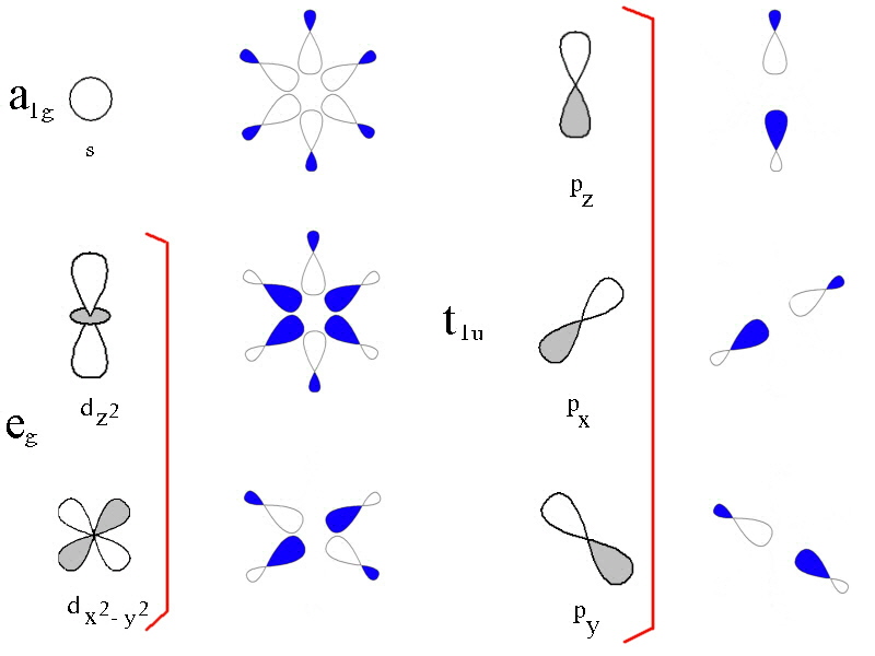
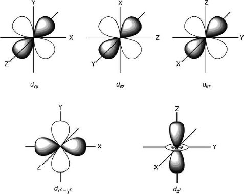
by J Börgel · 2016 · Cited by 21 — The splitting of the d-orbital based MOs for square planar complexes with π-acceptor ligands such as cyanide is qualitatively the same as for ... d orbital splitting in Tetrahedral geometry • Tetrahedral splitting, Δ t, is not as large as Δ o because only 4 ligands in tetrahedral vs. 6 ligands in octahedral • Δ o • As a result of this smaller splitting, in practice tetrahedral complexes are high spin LFSE can be calculated in The d orbitals can also be divided into two smaller sets. The d x2 - y2 and d z2 all point directly along the x, y, and z axes. They form an e g set. On the other hand, the lobes of the d xy, d xz, and d yz all line up in the quadrants, with no electron density on the axes. These three orbitals form the t 2g set. Therefore, chromium 3+ has three 3d-electrons. What is the number of 3d-electrons in cobalt 3+? 3. 3+Using your answer from Question 2, draw a d-orbital splitting diagram for low-spin Co similar to the one given for Cr3+ 3+in the introduction to this experiment. Almost all Co complexes are low-spin, with a minimum number of unpaired electrons.
(Color online) The d-orbital energy splittings of a ...
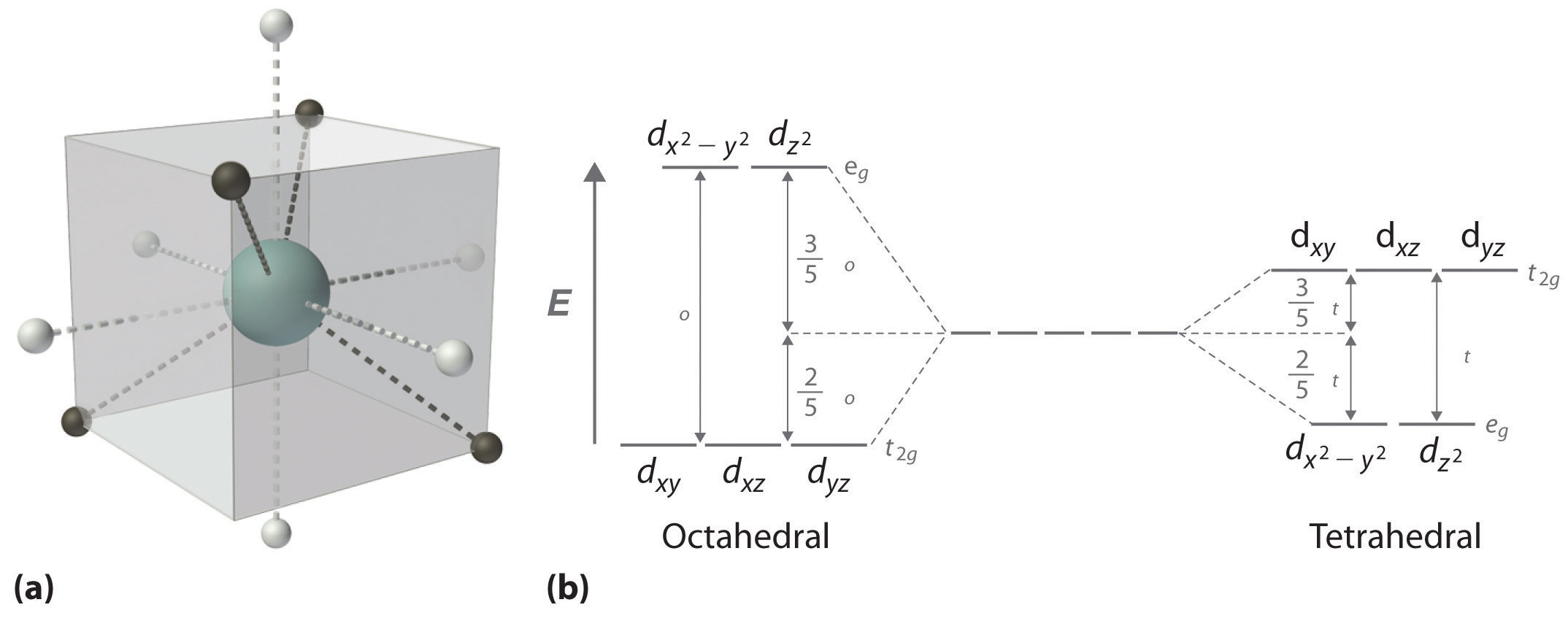
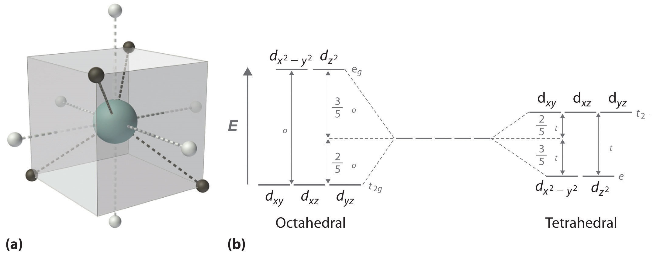
The d x 2-y 2 and d z 2 orbitals on the metal ion at the center of the cube lie between the ligands, and the d xy, d xz, and d yz orbitals point toward the ligands. As a result, the splitting observed in a tetrahedral crystal field is the opposite of the splitting in an octahedral complex.

Crystal field splitting for the octahedral coordinated Co ...
There is a variation on how to think about d orbital splitting diagrams that can be useful in deciding how the d electrons are configured in transition metal complexes. We can use the relative energy levels of the d orbitals in a given complex to calculate whether the overall energy would be higher or lower in a high-spin vs. a low-spin case ...
Why are tetrahedral complexes generally high spin? | Socratic
In this case, the d z 2 orbital drops even lower in energy, and the molecule has the following orbital splitting diagram. As a result of these distortions, there is a net lowering of energy (an increase in the ligand field stabilization energy) for complexes in which the metal has a d 7 , d 8 , or d 9 configurations, and thus electrons would ...

AAMC Chemistry Question Pack 1 (#14) Spoilers : Mcat
2 © K. S. Suslick, 2013 d-d Transitions: d1 -d9 of M(OH 2)6 n+ same εscale except d5,& d6. x100 rel. x2.5 rel. d1 d5 d2 d3 d4 d6 d7 d8 d9 © K. S. Suslick, 2013 d ...
.png)
pl explain crystal field theory - Chemistry - Coordination ...
The splitting of the d orbitals in these compounds is shown in the figure below. diagram. return to top. Use crystal field theory to generate splitting diagrams of the d-orbitals for metal 4. Square pyramidal d z2 dx2-y2 d xy d yz d xz. 5. Square planar d z2 dx2-y2 d. See the cases for octahedral, tetrahedral and square planar complexes.

Splitting of d-orbitals computed by ab initio ligand field ...
Part B. Draw the orbital diagram for the ion Co2+. Use the buttons at the top of the tool to add orbitals in order of increasing energy, starting at. Ni2+ Draw the d-orbital splitting diagrams for the octahedral complex ions of each of the following. a. Zn2+ b. Co2+ (high and low spin) c. Ti3+ the FT ligand.

Scientia ac Labore: Molecular Orbital Theory Notes III
But two of the d orbitals have lobes pointing along those axes - the 3d x 2 - y 2 and 3d z 2 orbitals. Those will feel more repulsion than the other three, which have lobes in between the axes. That means that two of the d orbitals will now have a higher energy than the other three - which is exactly what the diagram we have been using shows.
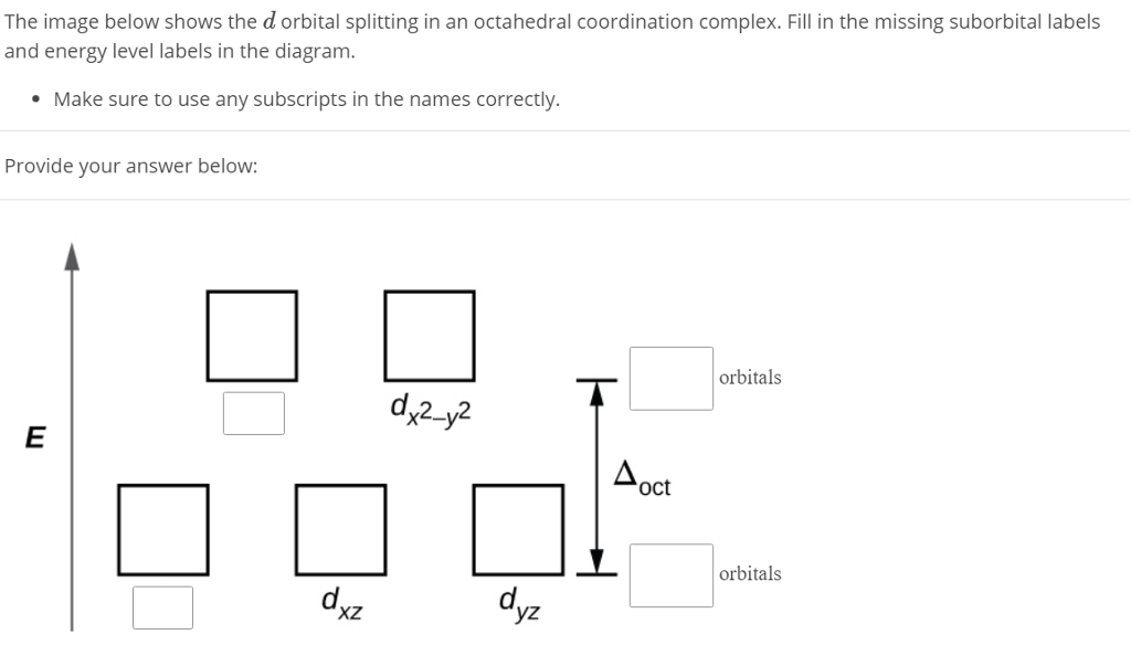
Solved: The Image Below Shows The D Orbital Splitting In A ...
follow me on Unacademy: https://unacademy.com/user/N_Huda

Schematic diagram of the d-orbital splitting in octahedral ...
02-12-2021 · The diagram shows the arrangement of the d electrons in a Cu 2+ ion before and after six water molecules bond with it. Whenever 6 ligands are arranged around a transition metal ion, the d orbitals are always split into 2 groups in this way - …
Tetragonal & square planar d orbital splitting | Science ...
We can use the d-orbital energy-level diagram in Figure 1.2. 1 to predict electronic structures and some of the properties of transition-metal complexes. We start with the Ti 3+ ion, which contains a single d electron, and proceed across the first row of the transition metals by adding a single electron at a time.

Crystal field splitting diagrams for Fe-O systems. and ...
I am trying to construct the diagram of $\mathrm{d}$ orbitals in the tetraammineplatinum(II) complex. According to the angular overlap model, $\mathrm{d}$ orbitals are going to look like those in the picture. However, planar square complexes are drawn completely differently according to other approaches and this makes me doubt the validity of my diagram.

Diagram of d-orbitals splitting when the cations (Fe 2 ...
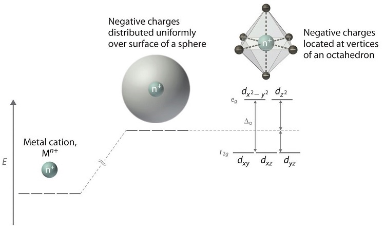
Metal d orbitals in an O h crystal field • If a transition metal ion is placed in a spherical field equivalent to the charges on six ligands, the energies of all five d orbitals would rise together (degenerately) as a result of the repulsions between the negative charges on the ligands and the negative charges of the

(a) AILFT orbital diagrams showing the calculated d ...
Octahedral CFT splitting: Electron diagram for octahedral d shell splitting. Crystal field stabilization is applicable to the transition-metal complexes of all geometries. The reason that many d 8 complexes are square-planar is the very large amount of crystal field stabilization that this geometry produces with this number of electrons.

Square Planar D Orbital Splitting Diagram
Placing a charge of −1 at each vertex of an octahedron causes the d orbitals to split into two groups with different energies: the dx2−y2 and ...6 May 2021 · Uploaded by Chuck WightIntroduction to Crystal Field... · Crystal Field Stabilization Energy
Ligand Field Theory
A general d-orbital splitting diagram for square planar (D 4h) transition metal complexes can be derived from the general octahedral (O h) splitting diagram, in which the d z 2 and the d x 2 −y 2 orbitals are degenerate and higher in energy than the degenerate set of d xy, d xz and d yz orbitals.

Square Planar D Orbital Splitting Diagram
SALCs for a tbp with the 5 d-orbitals assuming all the M-L distances are equal. Construct a d-orbital splitting diagram for a trigonal bipyramidal complex, assuming that the d-orbital energy, H dd, lies 2.5 eV above the ligand donor orbital energies, H LL. Perform a Hückel calculation on the complex, assuming that H
Crystal Field Theory - Chemistry LibreTexts
Crystal Field Splitting in an Octahedral Field eg Energy 3/5 o o 2/5 o t2g e g - The higher energy set of orbitals (d z2 and d x2-y2) t 2g - The lower energy set of orbitals (d xy, d yz and d xz) Δ o or 10 Dq - The energy separation between the two levels The eThe eg orbitals are repelled by an amount of 0 6orbitals are repelled by an amount of 0.6 Δo The t2gorbitals to be stabilized to the ...

Schematic of CF split 3d electronic level scheme for Fe 2 ...
The d-orbital splitting diagram is the inverse of that for an octahedral complex. 6. Page 6 of 33 The two sets of orbitals are labeled e and t2. The subscript g is not needed here, it is only used for systems that possess a centre of symmetry (tetrahedral systems do not have a centre of symmetry).

Orbital splitting of the d-energy levels within the cooper ...
d orbital splitting in Tetrahedral geometry d orbitals inscribed into a cube with octahedral ligand set (white circles) and tetrahedral ligand set (black circles). Octahedral ligands are on the face of the cubes whereas tetrahedral ligands are on the corners. Their interactions with the orbitals are thus opposite from each other.

Cartoon showing the d orbital splitting for molecular high ...
Platinum is not an exception to that statement. D ORBITAL SPLITTING FOR SQUARE PLANAR COMPLEXES The d orbitals look like this: We should recognize that since the ligands lie on the axes: The \mathbf(d_(x^2 - y^2)) orbitals experience the most repulsions. It is highest in energy. The \mathbf(d_(xy)) orbitals experience the second most.

Draw figure to show splitting of d orbitals in an ...
(b) The schematic d orbital splitting diagram for six-coordinate transition− metal complexes with O h , C 3 , and C 1 symmetry. from publication: Quenching ...

Non-octahedral Complexes - Chemistry LibreTexts
Crystal field theory (CFT) describes the breaking of degeneracies of electron orbital states, usually d or f orbitals, due to a static electric field produced by a surrounding charge distribution (anion neighbors). This theory has been used to describe various spectroscopies of transition metal coordination complexes, in particular optical spectra (colors).

4 Splitting of d orbitals in an octahedral ligand field ...
01-04-2015 · Ligand dissociation is expected to create a ‘localized hole on the metal’ 15 with a concomitant decrease in the d π –d σ * splitting (see the molecular-orbital diagram in Supplementary ...
27 D Orbital Diagram - Wiring Diagram List
M2+ with 8 d electrons: M = Pt Pt Cl NH3 Cl NH3 10.4 Angular overlap calculations for d 8 and d 9 ions show no energy difference between D4h and Oh when exclusively considering interactions. Both d 8 geometries have energies of -3e ; both d 9 geometries have energies of -6e . In general, stability constants decrease as more

CO in M-ZSM5
Crystal Field Splitting (CFS) Diagram | Strong and Weak Field Ligand | d- orbital splitting - 9#ForAnyQuestion_9840225631#Class_11_12_BSC_Coordination_Compou...

Schematic diagrams of the TM-d-orbital splitting after ...
d) [Co(CN) 6] 3- (low spin) Hexacyanocobaltate(III) ion. The oxidation state of Co is 3+ so the electron configuration is d 6 (t 2g 6) so LFSE = -24Dq + 2P. e) [Ni(NH 3) 4 Cl 2] cis-Tetraamminedichloronickel(II) or trans-tetraamminedichloronickel(II) The oxidation state of Ni is 2+ so the electron configuration is d 8 (t 2g 6 e g 2) so ...

The Chemistry of d- and f- Block: Crystal Field Theory

Crystal Field Theory - Chemistry LibreTexts
The rise of 3-d single-ion magnets in molecular magnetism ...

inorganic chemistry - How to calculate crystal field ...

d-orbital splitting for a square-based pyramid with the ...

(a) Qualitative d-orbital splitting diagram and electron ...
Crystal Field Theory - Chemistry LibreTexts

Schematic of the sequence of level splittings and ...
Pushing the limits of magnetic anisotropy in trigonal ...
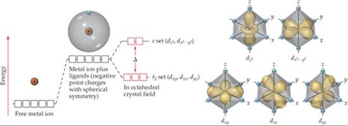
FIGURE 23.28 Energies of d orbitals in a free metal ion, a ...

High Spin and Low Spin Complexes - Chemistry LibreTexts

Scheme of the splitting of d orbitals in a square planar ...

Ligand fi eld splitting of Mo-d orbital in octahedral and ...
CHEM2P32 Lecture 9: Crystal Field Theory

Ligand field splitting for Mo imp d-orbitals produced by ...

6 Splitting of d orbital energy levels in ligand fields of ...
0 Response to "42 d orbital splitting diagram"
Post a Comment