41 timer relay wiring diagram
Relays Sockets Timers Contactors Terminal Blocks Circuit Breakers 800-262-IDEC (4332) t SA & Canada 833 Timers Timing Diagrams Overview Cycle 1 (power start, OFF first) When voltage is applied to the coil, the contacts remain in the off state and the set time begins. At the end of the set time, the contacts transfer to the on state 2 “NO” SCHEME FOR TIMER ON IN DELTA. B/R Phase. : Use only with above given wiring diagram. ! 896-6835 & 896-6838. 1.Always follow instructions stated in ...1 page
Time swicth for street light how to wire a contactor 8 steps with pin timer relay wiring diagram on lighting single phase motor starter switch selecting. A simple circuit diagram either of the two start buttons will close the contactor either of the stop buttons will open the contactor.

Timer relay wiring diagram
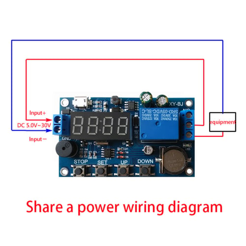
Oct 31, 2018 · Solid state timer relay electrical academia learning engineering 8 pin wiring diagram basic connection and function specifications technical data using time delay relays to cycle a traffic signal asymmetric cycler best supplier in china for 10 years geya 326 327 series on struthers dunn 555 ic digital 12v 24v 220v ato com ah3 n 3a super ... P3: Relay will turn ON for time OP after getting a trigger signal and then turn relay OFF.Module will reset and stop timing if it gets a trigger signal again during delay time OP. P4: Relay will turn OFF for time CL after getting a trigger sighal and then relay will turn ON for time OP.Relay will turn OFF after finish timing. Relay and contactor wiring diagram.Single Pole Contactor Relay Wiring Diagram 240v Single pole means that it can only control a single circuit and single throw means that there are only two positions the switch can be in one on and one off state mechanical relays do not The esd5 series is an accurate solid state delayed interval timer it offers a 1a steady 10a inrush output and is available ...
Timer relay wiring diagram. wire on Terminal 1, (See Diagram A). WIRING The # 950-1067 Timer/Relay may be used to replace either the 24 VAC input # 950-1060 or the 120 VAC input # 950-1065 Timer/Relays. The # 950-1067 is designed to accept either 24 VAC or 120 VAC control input signals on terminals 4 & 5. The control inputs are non-polarity sensitive. Dec 13, 2021 · 11 Pin Timer Relay Wiring Diagram. Author: Ryan Published Date: December 13, 2021 Comments: Leave a Comment on 11 Pin Timer Relay Wiring Diagram. Delay Timer With Push Button Timer Electrical Circuit Diagram 3 Way Switch Wiring. Star Delta Starter Wiring Diagram 3 Phase With Timer Electrical Online 4u Circuit Diagram Electrical Circuit Diagram ... Our channel provide the best electrical Video tutorials which is about electrical wiring ,home wiring ,transmission line HV, MV, LV, Motor control ,Sequence ... Macromatic TD-80222-41 On Delay Time Delay Relay TD-80222-41 is a programmable relay with an input voltage of 120V AC/DC at 50/60Hz. Time ranges from 1 to 1023 sec. Uses 8 pin 70169-D octal socket
How to Wire A Time Delay Relay Diagrams – wiring diagram is a simplified enjoyable pictorial representation of an electrical circuit. It shows the components of the circuit as simplified shapes, and the gift and signal contacts along with the devices. A wiring diagram usually gives guidance roughly the relative slant and bargain of devices ... voltage, the time relay (t) Upon application of input begins. At the end of the time delay (t), the output is energized. Input voltage must be removed to reset the time delay relay & de-energize the output. The timer function #1 is ON DELAY, it allows to supply power after a period of time (t). There are two Timer And Contactor Wiring Diagram Pdf. 240 volts ac and 480 volts ac are commonly used for these large pieces of. Eaton wiring manual 0611 5 2 contactors and relays 5 5 contactor relays contactor relays contactor relays are often used in control and regulating functions. Regardless of the type of time relay, as long as the timing time is equal to the set time, its output contacts will act to achieve the purpose of the timing control circuit. 4) For DC products, pay attention to wiring according to the circuit diagram and pay attention to the polarity of the power supply.
Step 4: Wiring new electronic timer • The new timer kit is connected to your charger with a two conductor wire assembly, which attaches to the timer with a three pin connector. Attach the connector to the new timer kit as shown in Figure E. • As shown in Figures A and B, attach the RED wire of the new wire assembly to the same point that the Please look at this picture: relay wiring diagram. Make sure to. ngk lamp timer 12v dc wire diagram need dentifying what ih8mud forum bj60glow ngk lamp timer 12v dc wire diagram sony ireleast info oe replacement parts. timer how to wire this delay relay switch electrical these diagrams came the circuit. The difference between relays and time delay relays is when the output contacts open & close: on a control relay, it happens when voltage is applied and removed from the coil; on time delay relays, the contacts will open or close before ... They are represented by the dotted lines in the wiring diagrams. Note that the user must provide the ... Question 2. A special class of electromechanical relays called time-delay relays provide delayed action, either upon power-up or power-down, and are commonly denoted in ladder logic diagrams by "TD" or "TR" designations near the coil symbols and arrows on the contact symbols.

Industrial Motor Control: Timing Relays
Jan 22, 2022 · 8 Pin Timer Relay Wiring Diagram. vivian.flatley January 22, 2022 Templates No Comments. 21 posts related to 8 Pin Timer Relay Wiring Diagram. 555 Timer Relay Circuit ...
DC 5V Real-Time Moment Delay Timer Relay Module Control ...
Wiring Diagram Pictures Detail: Name: time delay relay wiring diagram - 1 Minute Timer Circuit Diagram; File Type: JPG; Source: circuitdigest.com Size: 119.49 KB; Dimension: 1100 x 750

12V Relay With Timer Switch : 4 Steps - Instructables
Size: 34.73 KB. Dimension: 667 x 333. DOWNLOAD. Wiring Diagram Pics Detail: Name: dayton time delay relay wiring diagram - foxy wiring diagram for time delay relay the symbol daytontimer full size with motor symbol circuit. File Type: JPG. Source: gvsigmini.org. Size: 57.90 KB. Dimension: 1280 x 1024.

8 Pin Timer Wiring Diagram
8 Pin Timer Relay Wiring Diagram | Basic Timer Connection And Function |Three Phase Main Distribution Board Wiring | 3 Phase Distribution MDB Box Wiring Diag...

Double Pole Double Throw Relay Schematic Diagram
The diagram above is the 5 pin relay wiring diagram. There are different kinds of relays for different purposes. It can be used for various switching. Relay can be the best option to control electrical devices automatically. 5 pin is compromised of 3 main pins and an SPDT (single pole double throw).

Dave Lers : Workshop : Blog : Wiring a ST3PF Delay Off Relay
The time relay used in this video was purchased from:https://www.automation24.com/multifunction-timer-relay-selec-600xu-a-1-cu?previewPriceListId=1&refID=adw...
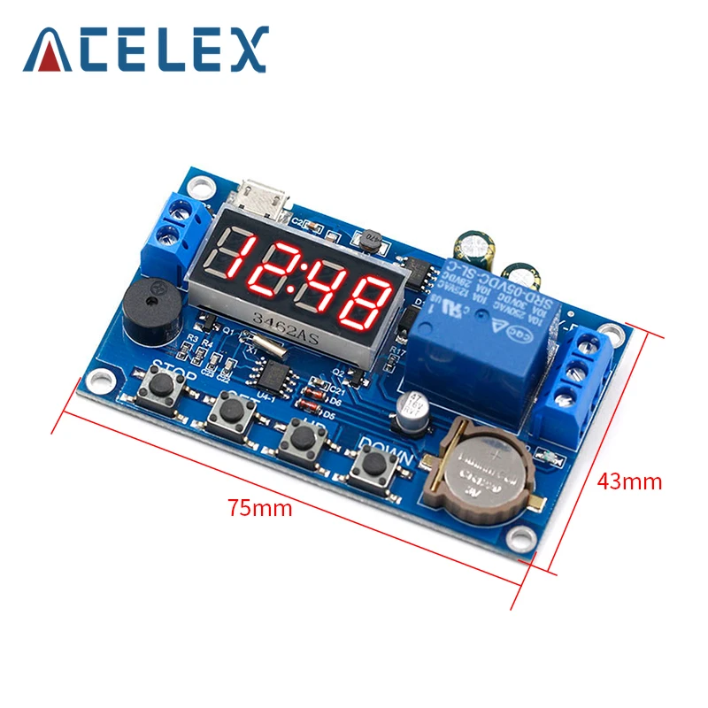
DC 5V Real time Timing Delay Timer Relay Module Switch ...
Time Relay Single-function time relay General µApplications-Suitable for applications where function and time requirements are know.-Time switch , possible to be used for pump decay time after switching heating off , switching of fans. µFunction Features ... Wiring Diagram Dimensions(mm) 1 2 25
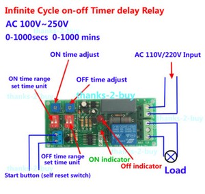
Details about 220V 110V AC Cycle Time Timer Switch Delay Relay ON OFF Repeat 1-1000mins adjust
How To Wire Pin Timers - 8 Pin Relay Wiring Diagram. Wiring Diagram comes with several easy to stick to Wiring Diagram Directions. It is intended to aid all the common consumer in creating a proper system. These instructions will likely be easy to grasp and use. With this particular guide, you may be able to see how each and every component ...
TIME DELAY RELAYS
8 Pin Timer Relay Wiring Diagram. angelo. October 13, 2021. Double Door Fridge Wiring Diagram Doubledoorfridgewiringdiagram In 2021 Refrigeration And Air Conditioning Air Conditioner Maintenance Double Door Fridge. Ah3 Timer Wiring Timer Basic Electronic Circuits Home Electrical Wiring. Contactor Wiring Diagram With Timer Diagram Relay Wire.
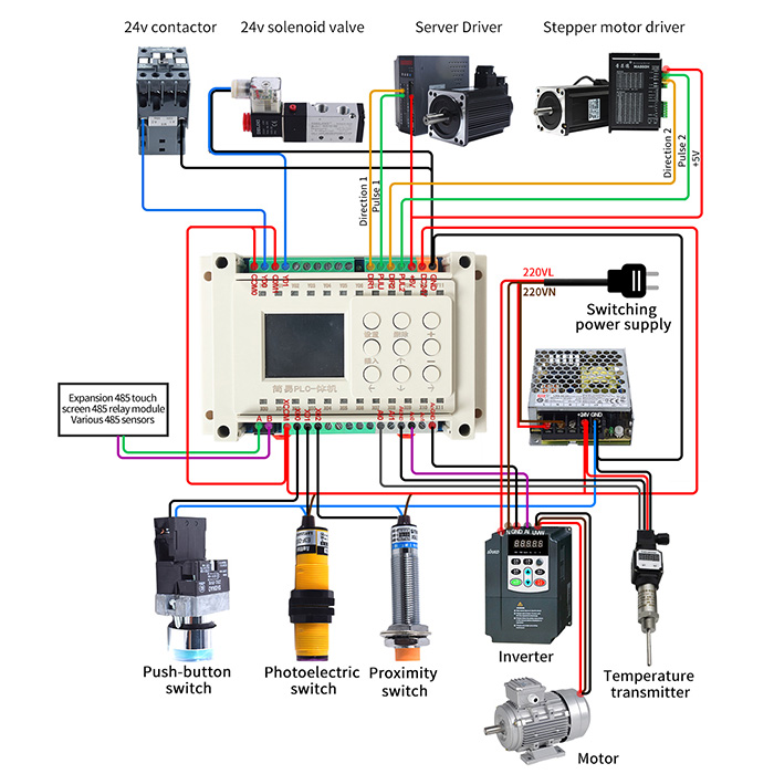
Programmable Timer Relay, 8-Input 8-Output, 12V/24V DC | ATO.com
13 series electronic step relays wiring diagrams 13 81 and 13 91 type 13 81 3 wire connection red led indication. It reveals the components of the circuit as simplified shapes and also the power and signal connections in between the tools. Pin On Relay Wiring Panel . Ah3 Delay Timer And Relay Timer Relay Home Electrical Wiring
ICS Time Delay Module Applications and Wiring
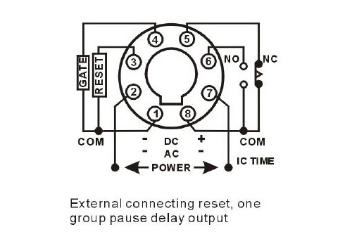
Aug 23, 2021 · 8 pin timer relay wiring diagram. The electric timer allows a light point to be turned on from one or more places in the room, and to leave this light point on for an adjustable period of time. The control points are pushbuttons with indicator lights (in order to be able to locate them in the event of extinction).

Time Delay Relay using 555 Timer IC
Off Delay Timer Relay Wiring Diagram. Amarante Pruvost. August 20, 2021. Find Instant Quality Info Now. Get Results from multiple Engines. This Post Is About The Staircase Timer Wiring Diagram In The Diagram I Use The On Delay Timer Finder 8 Pin Relay Re Electrical Circuit Diagram Timer Diagram.
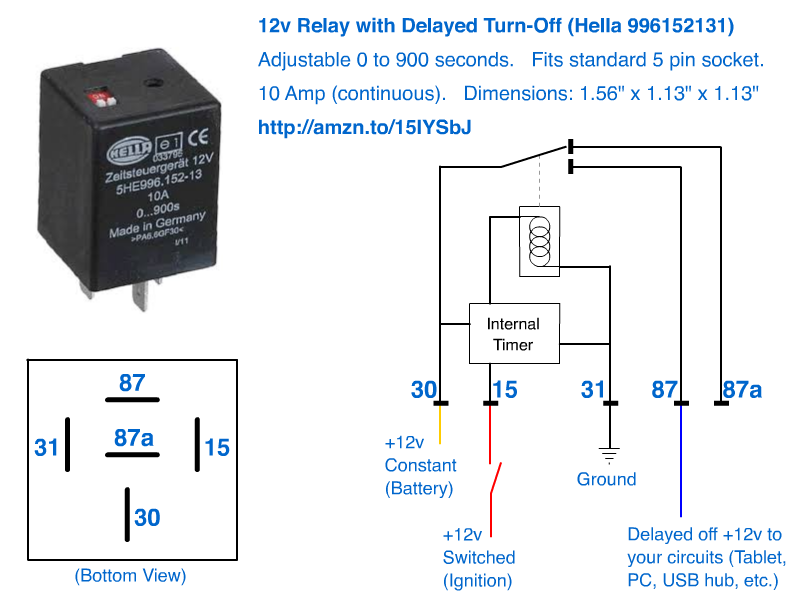
12v Delayed turn-off or turn-off (howto)
Time delay relays have a broad choice of timing ranges from less than one second to many days. There are Input Voltage: Control voltage applied to the input terminals (see wiring diagrams below). . 8 Pin Octal Base - On Delay / Interval.Power on delay, plus timing. With large transparent time setting knob for setting time easily, 8 pin solder ...
How to wire the electrician time relay?The physical wiring ...
ATO Time delay relay, Also available with 8-pin mounting socket for DIN Rail.The time relay is divided into the on delay timer and the off delay timer. Buy ...

This post is about the staircase timer wiring diagram. In the ...
Timer’s wiring diagram ..... 5 2.1 Connecting 5amp timer ... During the circuit design with the timer relay and variety of timer configuration, questions such as

20 Most Recent Amperite Dayton Solid State Timer On Questions ...
Wire the relay as follows: - Connect Pin 1 to Pin 4 - Connect Pin 4 to +12V - Connect Pin 2 to Pin 3 - Connect Pin 3 to Pin 7 - Connect Pin 7 to GND - Connect the two wires of the actuator to Pins 5 and 6, so when the relay is deactivated, the actuator is retracted. If the relay extends, just flip the connections on 5 and 6.

12V Time Delay Relay Circuit
The above circuit diagram is for the 1-minute timer circuit. This Touch Switch Circuit Diagram is built around a 555 timer by making use of the default properties of the Pins of the 555 Timer IC. This will give an output at Pin 2 after about 9 Hours. Wiring diagram for timer and contactorSterilmatic fails to operate at all.

How to wire off delay timer | Timer, Electrical wiring ...
Relay and contactor wiring diagram.Single Pole Contactor Relay Wiring Diagram 240v Single pole means that it can only control a single circuit and single throw means that there are only two positions the switch can be in one on and one off state mechanical relays do not The esd5 series is an accurate solid state delayed interval timer it offers a 1a steady 10a inrush output and is available ...

China Power Off Delay Timer Relay Manufacturers, Suppliers ...
P3: Relay will turn ON for time OP after getting a trigger signal and then turn relay OFF.Module will reset and stop timing if it gets a trigger signal again during delay time OP. P4: Relay will turn OFF for time CL after getting a trigger sighal and then relay will turn ON for time OP.Relay will turn OFF after finish timing.

How to wire this delay relay switch - Electrical Engineering ...
Oct 31, 2018 · Solid state timer relay electrical academia learning engineering 8 pin wiring diagram basic connection and function specifications technical data using time delay relays to cycle a traffic signal asymmetric cycler best supplier in china for 10 years geya 326 327 series on struthers dunn 555 ic digital 12v 24v 220v ato com ah3 n 3a super ...

Timer Relay - 10 minutes

12 Volt Double-Pole Double-Throw Timer Relay | Firgelli
Time Delay Relay TDR 120VAC 24VDC
ICS Time Delay Module Applications and Wiring

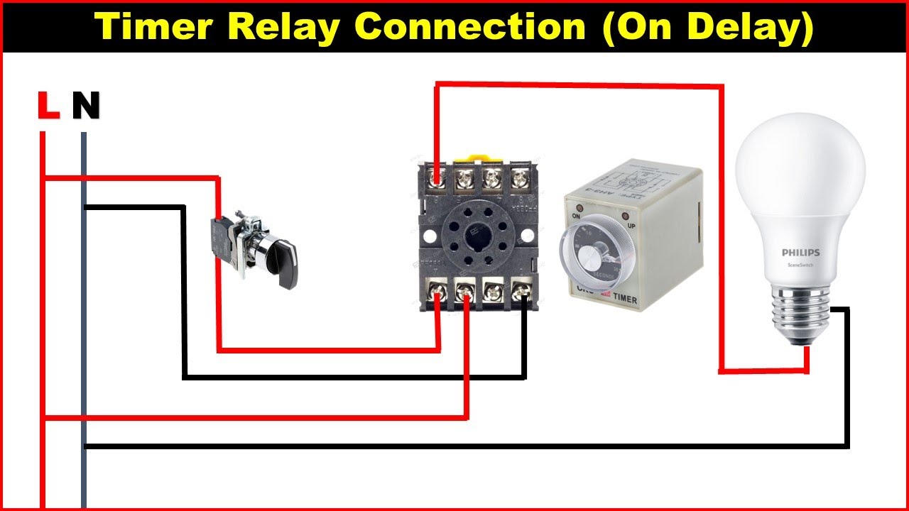
On Delay Timer Connection Diagram and Testing - ETechnoG
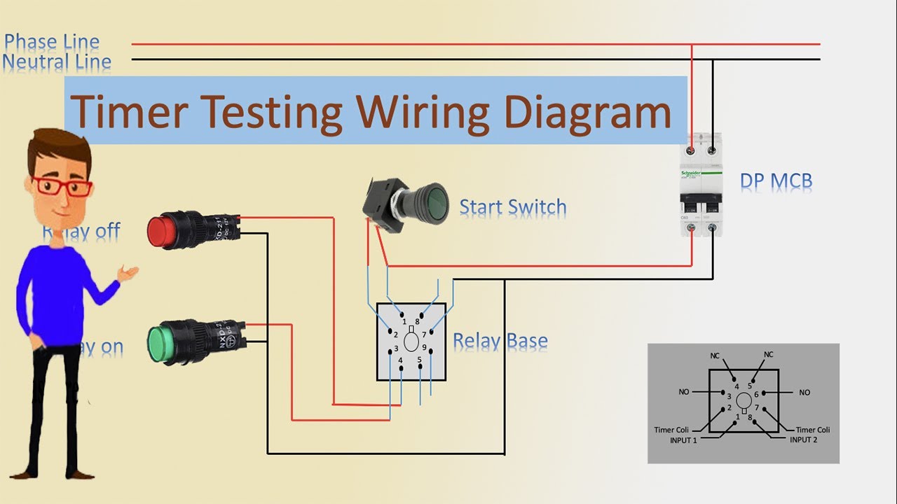
Timer Testing Wiring Diagram | Timer | Timer Wiring | Timer Wiring

How to connect and set analog timer relay
How Do I? - Glow plug timer relay | Land Rover UK Forums

On Delay Timer Connection Diagram and Testing - ETechnoG

Learning Engineering: 8 Pin Timer Relay Wiring Diagram ...

How to wire Pin timers

How to wire AH3-3 timer

How to wire Pin timers
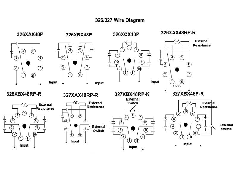
326/327 Series - Time Delay Relays On Struthers-Dunn

JS14P mini time relay timing Control Relay digital display ...

Time Delay Relay using 555 Timer, Proteus Simulation and PCB ...
8 Pin Timer Relay Wiring Diagram | Basic Timer Connection And Function |
Time Delay Relay TDR 120VAC 24VDC

Wiring Diagram | Timer Relay | Flickr
9050JCK60V24 - Timing Relay, Type JCK, plug In, on delay ...
Digital Timer Relay, 8 Pin, 24V DC/110-240V AC | ATO.com
0 Response to "41 timer relay wiring diagram"
Post a Comment