40 pressure switch wiring diagram
Nov 15, 2021 · 3 phase air compressor pressure switch wiring diagram. 3 Phase Air Compressor Wiring Diagram wiring diagram is a simplified welcome pictorial representation of an electrical circuit.Float Switch Installation Wiring Control Diagrams Apg. Basic control circuits three wire electric equipment air compressor wiring home model engine machinist forum 3 … Aug 03, 2021 · Pressure Switch Wiring Diagram Air Compressor And 2013 05 28 in Pressure Switch Wiring Diagram Air Compressor image size 1024 X 721 px and to view image details please click the image. Connect one end of this cable to the two outside terminals of the pressure switch. Pin On Vw 40 psi Factory Set Cut-Out […]
Apr 06, 2020 · DOWNLOAD. Wiring Diagram Pictures Detail: Name: water pump pressure switch wiring diagram – Well Pump Pressure Switch Wiring Diagram Exquisite Stain Psidekick Install And. File Type: JPG. Source: teenwolfonline.org. Size: 90.88 KB. Dimension: 598 x 366. DOWNLOAD. Wiring Diagram Sheets Detail:

Pressure switch wiring diagram
Touch the pressure switch terminals with each tester probe. 4. The multimeter will show 0 or close to 0 which indicates no resistance. 5. But, if the reading is higher then the pressure switch is busted up. 6. You have to replace or repair the air compressor pressure switch. Care To Share! Han. wiring diagram to determine the proper fourth gear pressure switch location. See Figures 1, 2 and 3. Install the switch and torque to 8 foot-pounds. Additional OEM switches may be left in place even though they will not be utilized. INSTRUCTIONS Figure 1: 700R4 Street/Strip Wiring Diagram Wiring Diagram Book A1 15 B1 B2 16 18 B3 A2 B1 B3 15 Supply voltage 16 18 L M H 2 Levels B2 L1 F U 1 460 V F U 2 L2 L3 GND H1 H3 H2 H4 F U 3 X1A F U 4 F U 5 X2A R Power On Optional X1 X2115 V ... Pressure & Vacuum Switches Liquid Level Switches Temperature Actuated Switches Flow Switches Speed (Plugging) FF R F R Anti-Plug N.O. N.C.
Pressure switch wiring diagram. Oct 02, 2019 · A wiring diagram is normally found on the inside of the cover. Loosen (do not remove) the screws on the pressure switch terminal with a screwdriver by turning in a counterclockwise direction. Feed wires from the pump motor and main power supply through the openings on either side of the switch. 4 Pin Pressure Switch Wiring Diagram//How to work trinary switch .Old Car A/c wiring diagram with 4pin relay #new car AC fitting wiring diagram#manual car AC... Mar 31, 2018 · March 31, 2018 by headcontrolsystem. Collection of well pump pressure switch wiring diagram. A wiring diagram is a simplified traditional photographic representation of an electric circuit. It reveals the parts of the circuit as simplified forms, and the power as well as signal connections between the tools. A wiring diagram usually gives info ... PSD25 Wiring Diagrams Cable Assembly Wiring Colors: Pin 1 - Brown Pin 2 - White Pin 3 - Blue Pin 4 - Black Note: wiring colors are based on ... MPS25-1C-D30A Pressure switch, 6 to 30 psig setpoint range, 1/4” NPTmale port, 3A SPDT switch output 1 0.9 $89.00 MPS25-1C-D60A Pressure switch, ...
Water Pump Pressure Switch Wiring Diagram – square d water pump pressure switch wiring diagram, water pump pressure control switch wiring diagram, water pump pressure switch wiring diagram, Every electrical structure is composed of various different components. Each part should be placed and connected with other parts in particular way. Otherwise, the structure won’t work as it should be. Wiring Diagrams Wiring (connection) diagram – a diagram that shows the connection of an installation or its component devices or parts. Wiring diagrams show, as closely as possible, the actual location of each component in a circuit, including the control circuit and the power circuit. Oct 22, 2018 · Dodge Durango Wiring Diagram. Square D Pumptrol FSG well tank pressure switches are the industry standard for household well installations. They are easy to install, have adjustable cut-in and cut-out settings and can control both submersible pumps and jet pumps. Features: Factory Set Cut-In Pressure: 40 psi Factory Set Cut-Out Pressure: 60 psi ... Dec 18, 2018 · Danfoss Pressure Switch Wiring Diagram. CS pressure switches have a built-in pressure operated, three-pole switch. The contact position of which depends on the pressure in the connector and the. LP signal option: A-B close on …
New Slide-out Switch Wiring Diagram 12 Room Bar Measurement Chart 13 Instructions 13 The Lippert Electric Through Frame Slide-out System is a rack and pinion guide system, utilizing an electric ball Jack room up just enough to remove pressure off the gear pack. 4. Wiring Diagram - Fig. Pressure Sensor & Wiring Diagram. Wiring Diagram Book A1 15 B1 B2 16 18 B3 A2 B1 B3 15 Supply voltage 16 18 L M H 2 Levels B2 L1 F U 1 460 V F U 2 L2 L3 GND H1 H3 H2 H4 F U 3 X1A F U 4 F U 5 X2A R Power On Optional X1 X2115 V ... Pressure & Vacuum Switches Liquid Level Switches Temperature Actuated Switches Flow Switches Speed (Plugging) FF R F R Anti-Plug N.O. N.C. wiring diagram to determine the proper fourth gear pressure switch location. See Figures 1, 2 and 3. Install the switch and torque to 8 foot-pounds. Additional OEM switches may be left in place even though they will not be utilized. INSTRUCTIONS Figure 1: 700R4 Street/Strip Wiring Diagram Touch the pressure switch terminals with each tester probe. 4. The multimeter will show 0 or close to 0 which indicates no resistance. 5. But, if the reading is higher then the pressure switch is busted up. 6. You have to replace or repair the air compressor pressure switch. Care To Share! Han.
Image from page 167 of "The Street railway journal" (1884)

Squared Pressure Switch Wiring Diagram

Closeup of skeleton foot model
Square D Pumptrol Pressure Switch Wiring Diagram

Pressure Switch Wiring Diagram Air Compressor - Wiring ...

Image from page 601 of "The Street railway journal" (1884)

Image from page 210 of "The Street railway journal" (1884)

Wiring Diagram For Well Pressure Switch
![[DIAGRAM] Irrigation Pressure Switch Wiring Diagram FULL ...](https://ricardolevinsmorales.com/wp-content/uploads/2018/09/square-d-pumptrol-pressure-switch-wiring-diagram-square-d-manual-motor-starter-wiring-diagram-chromatex-rh-chromatex-me-square-d-pressure-switch-wiring-9c.jpg)
[DIAGRAM] Irrigation Pressure Switch Wiring Diagram FULL ...

How It Works: Pressure Switch - Rolair
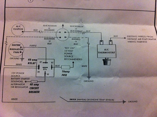
2nd Gen Camaro LS1 Vintage Air Trinary Switch Wiring ...
Electrocardiogram

Oil Pressure Safety Switch Wiring Diagram - General Wiring ...

Air Pressure Switch Wiring Diagram - Wiring Diagram And ...

Image from page 66 of "Railway and locomotive engineering : a practical journal of railway motive power and rolling stock" (1901)
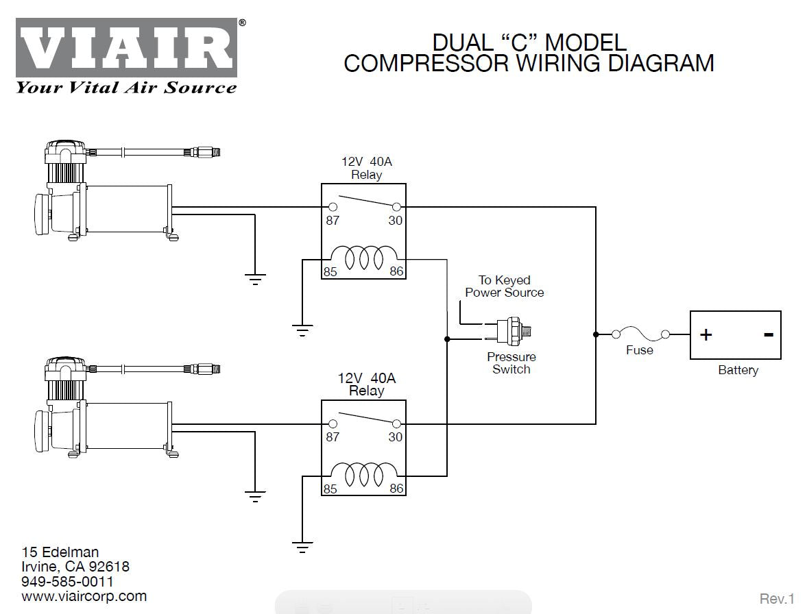
Viair Pressure Switch Wiring Diagram

Image from page 193 of "Report of the Electric Railway Test Commission to the president of the Louisiana Purchase Exposition" (1906)

Image from page 591 of "The Street railway journal" (1884)
Water Pressure Switch Wiring Diagram - Installing A ...

Image from page 42 of "Investigation of the aluminum cell : the rectifier" (1913)

Pressure Switch Ratings - Electrical - DIY Chatroom Home ...

Refrigeration Pressure Switches [ HVAC Air Conditioner and ...
Danfoss Pressure Switch Wiring Diagram

Ge Rr7 Relay Wiring Diagram - Wiring Diagram Database

Image from page 414 of "Electric railway journal" (1908)

Image from page 167 of "Practical wireless telegraphy; a complete text book for students of radio communication" (1917)

Water Well Pressure Switch Wiring Diagram Gooddy Org New ...

CR4 - Thread: Differential Pressure Switch Wiring

Air Compressor Pressure Switch Wiring Diagram - Collection ...

Square D Well Pressure Switch Wiring Diagram - Complete ...
Changed Oil Pressure Switch... now Engine Sounds Terrible ...
27 Square D Well Pump Pressure Switch Wiring Diagram ...

Square D Air Compressor Pressure Switch Wiring Diagram ...

120v from 240v line? - DoItYourself.com Community Forums

Closeup of skeleton hand model

Model organ

Pressure Switch 4 Wire Well Pump Wiring Diagram Database

Wiring Diagram For Well Pressure Switch

Water Pressure Switch Wiring Diagram - Installing A ...

Well Pressure Switch Wiring Diagram Database
0 Response to "40 pressure switch wiring diagram"
Post a Comment