37 5 wire door lock actuator wiring diagram
5 Wire Door Lock Actuator Wiring Diagram – wiring diagram is a simplified pleasing pictorial representation of an electrical circuit. It shows the components of the circuit as simplified shapes, and the power and signal associates in the company of the devices. WIRING 1. Run all the wires to the location of the door lock module. Be sure to mount the module in a dry place (under the dash). 2. Connect the 5 wires from the actuator to the wire harness in accordance with the same color. 3. Connect the separate black wire to a chassis ground (body metal). 4.
The Dexter DX Series actuator splices into your trailer's wiring. Follow the diagram below when connecting the wires. 12-Gauge wire is required, but 10-gauge wire is recommended to ensure the best performance. K71-651-00 Dexter Axle DX Series ElectroHydraulic Brake Actuator - Disc Brakes - 1,600 psi

5 wire door lock actuator wiring diagram
2015 Sierra door lock wiring diagram. Sign up for FREE! Become a GM-Trucks.com Member Today! In 20 seconds you can become part of the worlds largest and oldest community discussing General Motors, Chevrolet and GMC branded pickups, crossovers, and SUVs. From buying research to owner support, join 1.5 MILLION GM Truck Enthusiasts every month who ... Dec 28, 2019 · 5 Wire Central Locking Actuator Wiring Diagram Wiring Diagram Nmax 8 Yamaha Fresh 5 Wire Central Locking Actuator. 5 Wire Central Locking Actuator Wiring Diagram – wiring diagram is a simplified within acceptable limits pictorial representation of an electrical circuit. It shows the components of the circuit as simplified shapes, and the capacity and signal connections amongst the devices. I sent you the wiring diagram for the pins. Top two are for the motor, you switch polarity to spin motor forward and backwards using a DPDT switch. Lower left is 2wd indicator, lower middle is 4wd indicator, lower right is ground for the indicator pins. As far as indicator for 2/4wd I wired mine up to lights since I went prerunner to 4wd.
5 wire door lock actuator wiring diagram. This lock is rated at 1200 pounds holding force, and is supplied with a kit of fixing brackets & armature plate. Magnetic Lock Wiring Diagram. Magnetic Lock Wiring Diagram Much like the door access control system diagram above, the mag lock wiring diagram relies on a few simple basics: electricity supply, switches, and, of course, locks. Dec 12, 2021 · External Limit Switch Kit For Actuators Linear Actuator Actuator Switch. Door Locks 5 Wire Alternating 12 Volts Positive Type C Relay Wiring Diagram Car Door Lock Electric Lock Door Lock System. View Toyota Corolla Car Stereo Wiring Diagram Pics In 2021 Corolla Car Toyota Corolla Car Stereo. Door Locks - 5 Wire Alternating 12 Volts Positive (Type C) Relay Wiring Diagram. How to Wire Automotive SPDT Relays. Door Locks - 5 Wire Alternating 12 Volts ... Power Door Lock Actuator Wiring Diagram Wire Switch, Door Switch, Jeep Doors ... 12V 30/40 amp 5 pin SPDT automotive relay with wires + harness socket 5 pcs.
Power Door Locks & Wiring DiagramAmazon Printed Bookshttps://www.createspace.com/3623931Amazon Kindle Editionhttp://www.amazon.com/Automotive-Electronic-Diag... 5 Wire Door Lock Actuator Wiring Diagram Wire Center Best Of Power Door Locks Diagram Car Door Lock . Es200 Wiring Diagram Connection Scheme Automatic Sliding Doors Diagram Automatic Door . 18 Electrical Door Interlock Wiring Diagram Wiring Diagram Wiringg Net Diagram Electrical System Wire . Door Lock Actuator 5 Wire. that trigger a module with relays to lock and unlock the other doors. in the vehicle or a simple push-button. This door lock actuator will work with most security systems. release using a simple push-button switch or relays. The output shaft can rotate 360 degrees. 2014 Crew cab door lock wiring diagram. Can any one provide me with a wiring diagram for the door locks on a 2014 crew cab xlt. The drivers side door will unlock but not lock the doors. Passenger side works fine as do the key pad and key fob. I tried the passenger side switch on the drivers side and nothing. I figure a broken wire in the jamb.
View Universal 5 Wire Door Lock Actuator Wiring Diagram Images · A First Appearance At A Circuit Diagram May Be Complex, However If You Could Review A Train Map, ... In my case, I hooked both yellow wires up to ground. Connect the lock wire (WHITE) to the light green wire on the lock actuator box. Connect the unlock wire (WHITE-black) to the dark green wire on the lock actuator box. Connect one brown wire to the left signal flasher (green-black) and the other brown wire to the right signal flasher (green ... This is the basic wiring diagram for SAFE electric fuel pump wiring. The diagram is color coded per circuit and only a few things may need to be said. Fuel pump wiring for the RED circuit is generally going to carry a much higher current than the relay. So use a larger gauge wire for lower voltage drop. For big pumps try 12 gauge, for smaller ... 5 Wire Door Actuator Diagram Wiring Diagram Box. Car Central Locking Wiring Diagram Wiring Diagram Long. I Have A 1990 Ford Mustang Gt I Need The Process For Replacing The. ... Chevy Power Door Lock Actuator Wiring Wiring Diagram Schematics. Ford Oem 12 16 Focus Front Door Lock Actuator Motor F1ez58219a64a Ebay.
brown wooden door frames
17.11.2014 · Watch the video. The upper actuator is located behind and below the removed elbow. Figure 7. Remove air duct. (Related Article: Actuator Installation - Ford-Trucks.com) Step 6 - Remove screws securing actuator to blend door shaft. Remove the screws and replace the blend door actuator. It self-indexes and should drop in. Figure 8.

Central Locking 5 Wire Door Lock Actuator Wiring Diagram ...
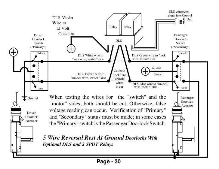
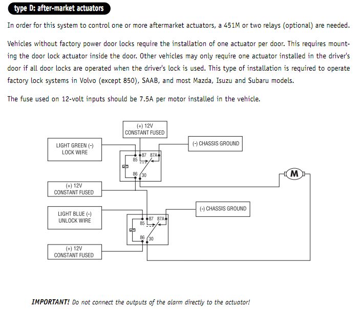
Door Locks - Actuators / Reverse Polarity - Positive Switch/Trigger (Type D) Relay Wiring Diagram. Both motor legs rest at ground at the relays. To lock or unlock the vehicle, polarity is changed on one motor leg via a positive pulse from a switch, alarm, keyless entry, etc. to the coil of the respective relay.
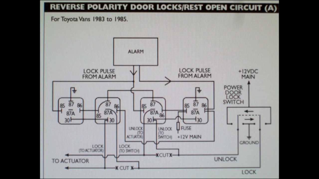
How to wire 5 wire reversing polarity door locks in early ...
Dec 27, 2020 - 5 Wire Door Lock Actuator Wiring Diagram Wire Center Best Of Power

Aftermarket Power Door Locks Not Working Properly, Can you ...
Power Door Lock Wiring Diagram. 5 Wire Door Lock Actuator Wiring Diagram wiring diagram is a simplified pleasing pictorial representation of an electrical circuitIt shows the components of the circuit as simplified shapes and the power and signal associates in the company of the devices.

5 Wire Car Door Lock Actuator Wiring Diagram Collection
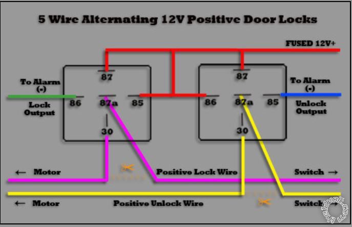
May 04, 2020 · Door Locks - 5 Wire Alternating 12 Volts Positive (Type C) Relay Wiring Diagram. The switch, when moved in either direction, applies both power and ground directly to motor legs without the use of any relays. Except, at the switch in this case, both motor legs rest at ground . Therefore it is only necessary to change the polarity of one motor leg to lock or unlock the vehicle.
Door Lock Wiring
Standard ";5-Wire" Relay Wiring . ... Multiplexed Door Lock Wiring Diagram. ... when the switch locks the doors, and the other wire will pulse negative ...21 pages

Chrysler 5-Wire Trunk Pop
07.07.2020 · A door lock actuator is basically a reversible motor (or a solenoid on some vehicles) with gears that operate the door lock. The concept of a door lock actuator works great—until it doesn’t. When the actuator fails (or starts to fail), you’ll likely notice one or more symptoms that make your daily commute less pleasant.
56 Reverse Polarity Door Lock Relay Wiring - Wiring ...
5 Wire Door Lock Actuator Wiring Diagram Added actuators type d the two wires of the actuators will normally rest at ground if wired as shown in this diagram but may rest at 12v dcpolarity changes on one wire during lock and on the other wire during unlock. 10 On the EX the wire is located at the drivers power window switch.
Stealth car alarm install - 3rd Generation Acura Integra DC
Door Locks - 5 Wire Alternating 12 Volts Positive (Type C) Relay Wiring Diagram. How to Wire Automotive SPDT Relays. Door Locks - 5 Wire Alternating 12 ...
5 Wire Car Door Lock Actuator Wiring Diagram Collection
"Type 2 Negative" Door Lock Test (Most Imports, some newer Fords) Probe both door lock wires going to the door lock switch these wires are usually located in the driver's kick panel. Attach one end of your test light to +12V using the vehicle's door lock controls activate the lock then the unlock test-ing both wires one at a time.
Central locking wiring for Honda Civic from LF-Q025A alarm ...
778 RELAY for TYPE C DOOR LOCKS Units without On Board Door Lock Relays: 778 RELAY for TYPE C DOOR LOCKS Reverse-Polarity, relays and harness: CHILD SAFETY LOCK diagram: CHRYSLER TRUNK RELEASE DIAGRAM (5-WIRE) DIODES and How They Work Page 1: DIODES and How They Work Page 2: FORD 5-WIRE TRUNK RELEASE DIAGRAM: …
Wiring up aftermarket door lock actuators and alarm - S-10 ...
Nov 28, 2020 · Diagram-5-Wire-Door-Lock-Actuator-Wiring-And-Wellreadmerhwellreadme – 5 Wire Motor Wiring Diagram. The diagram offers visual representation of a electric structure. On the other hand, this diagram is a simplified variant of the arrangement. It makes the process of building circuit easier.
Door Locks - 5 Wire Alternating 12 Volts Positive (Type C ...
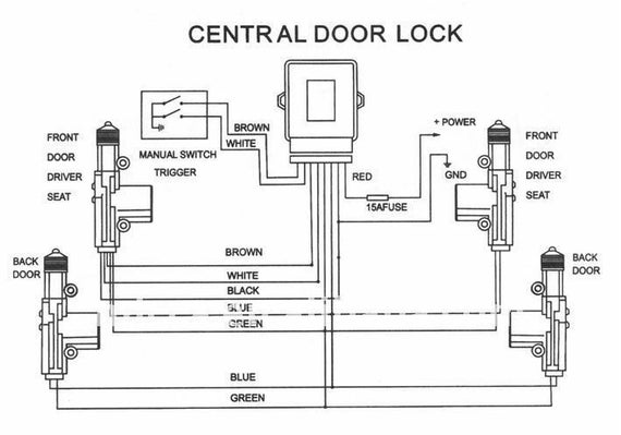
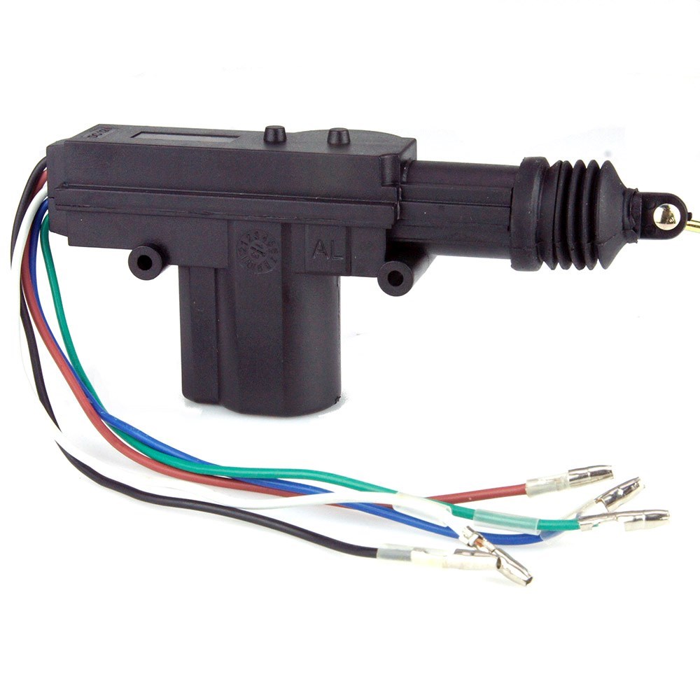
Central Door Lock Actuator with 5 wires, with 360 degree rotation heads for easy installation. Usable with remote control and alarm system. More convenience and security Converts manual door locks to full power. Car power door lock system accessories for master actuator, 5 wires suitable for the master door (drivers seat).
Universal Door Lock Actuator Wiring Diagram - Wiring ...
if you are doing a conversion from non power to power locks use the 5 wire to control the other locks. green lock, blue unlock. wire up the relays like your diagram and run it to the blue and green wire on the actuator. the actuator on the passenger door cut off the white brown and black wire and on the driver door ground the black wire and tie …

5 Wire Door Lock Relay Diagram - General Wiring Diagram
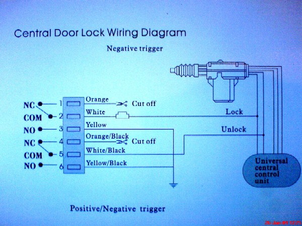
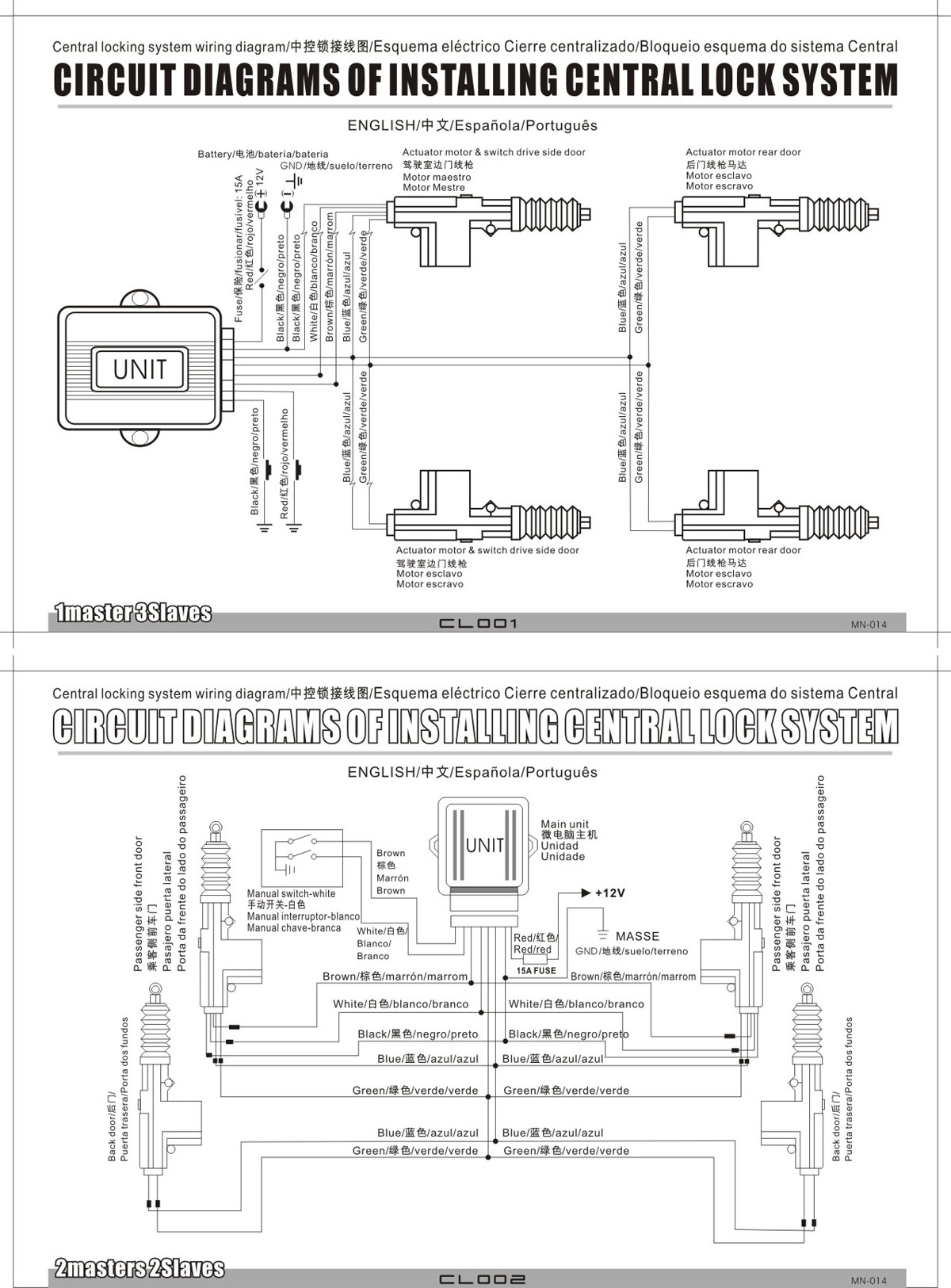
The Master actuator (5 wires) is mounted on the driver's door so when you manually lock/unlock using the factory manual door lock, the locking system is triggered and all other doors (the slaves with 2 wires each) will lock/unlock all passenger door(s) in sync with the driver's door.

5 Wire Door Lock Actuator Wiring | schematic and wiring ...
should swap blue and green wire (blue wire from actuator to green wire from bunch). CAUTION: Make sure that wires are installed without being pinched by screen mechanism or screws, which might cause short circuit. 4. Push down and up front door lock bolt (5-wires actuator), to check if all actuators are

5 Wire Door Lock Actuator Wiring | schematic and wiring ...
Central Locking 5 Wire Door Lock Actuator Wiring Diagram from static-cdn.imageservice.cloud. To properly read a wiring diagram, one provides to learn how the particular components within the program operate. For instance , in case a module will be powered up and it also sends out the signal of fifty percent the voltage and the technician would ...

Trunk Lock Actuator Wiring Diagram - Complete Wiring Schemas
19.11.2017 · the blend door by hand. If it moves freely, you’ve eliminated the blend door itself as the cause. Using a fused jumper wire, provide power and ground to the actuator using the wiring diagram to see if the motor operates.

5 Wire Door Lock Actuator Wiring Diagram For Your Needs
Universal 5 Wire Door Lock Actuator Wiring Diagram Source: www.civic-eg.com READ Split Phase Motor Wiring Diagram Database Read cabling diagrams from unfavorable to positive plus redraw the signal being a straight collection.

empty concrete road
Version. Listed below is the vehicle specific wiring diagram for your car alarm, remote starter or keyless entry installation into your 2004-2005 Dodge Ram . This information outlines the wires location, color and polarity to help you identify the proper connection spots in the vehicle. Please be sure to test all of your wires with a digital ...

Aftermarket Power Door Lock Wiring Diagram - Power Lock
5 wire door lock actuator wiring diagram wiring diagram is a simplified pleasing pictorial representation of an electrical circuit it shows the components of the circuit as simplified shapes and the power and signal associates in the company of the devices.

four persons standing on seashore near rock form of arch
The Driver's door actuator has 5 wires coming from it. The other actuators have the typical 2 wires (green and blue). Question 1. The actuator kit came with a small controller box. Is that to be used to connect to the alarm instead of wiring the actuators through 2 40amp relays? Question 2. Why the 5 wires coming from the driver's door actuator?
5 Wire Car Door Lock Actuator Wiring Diagram Collection
Technical Wiring Diagrams. View or Download PDF File. ATTENTION: This wiring information is being provided free of charge and on an "as is" basis, without any representation or warranty. It is your responsibility to verify any circuit before interfacing with it by using a digital multimeter.

I am installing 524T universal door lock actuators, as ...
Here is an easy 5 wire setup for anyone to use in any vehicle without the use of any relays

Wiring Diagram For Central Locking Actuator
When the switch is closed, the green/white wire sends a signal to terminal 6 of the PSE, either from Green/red, or ground (brown). The PSE either sends vacuum or pressure to the door lock actuator. The green/red gets power from F4f11, so fuse 11 in the rear fuse box. Other wires at the switch are only for lighting.

Door Lock Actuator Wiring Diagram - Wiring Diagram Schemas
23.11.2021 · Internal wiring for each junction block is also provided for better understanding of connection within a junction block. Wiring related to each system is indicated in each system circuit by arrows (from_, to_). When overall connections are required, see the Overall Electrical Wiring Diagram at the end of this manual.

green wooden storm glass door close
I sent you the wiring diagram for the pins. Top two are for the motor, you switch polarity to spin motor forward and backwards using a DPDT switch. Lower left is 2wd indicator, lower middle is 4wd indicator, lower right is ground for the indicator pins. As far as indicator for 2/4wd I wired mine up to lights since I went prerunner to 4wd.

35 Door Lock Actuator Wiring Diagram - Wiring Diagram Database
Dec 28, 2019 · 5 Wire Central Locking Actuator Wiring Diagram Wiring Diagram Nmax 8 Yamaha Fresh 5 Wire Central Locking Actuator. 5 Wire Central Locking Actuator Wiring Diagram – wiring diagram is a simplified within acceptable limits pictorial representation of an electrical circuit. It shows the components of the circuit as simplified shapes, and the capacity and signal connections amongst the devices.
Trunk Lock Actuator Wiring Diagram - Complete Wiring Schemas
2015 Sierra door lock wiring diagram. Sign up for FREE! Become a GM-Trucks.com Member Today! In 20 seconds you can become part of the worlds largest and oldest community discussing General Motors, Chevrolet and GMC branded pickups, crossovers, and SUVs. From buying research to owner support, join 1.5 MILLION GM Truck Enthusiasts every month who ...

Door Lock Actuator Wiring Diagram : Universal Power Door ...

brown wooden door

5 Wire Door Actuator Wiring Diagram - easywiring

yellow wooden door is close

Universal Door Lock Actuator Wiring Diagram For Your Needs

Central Locking 5 Wire Door Lock Actuator Wiring Diagram ...
Car Auto Heavy Duty Power Door Lock Actuator Motor 2 Wire ...

red wooden door of blue, red, and brown painted wall
0 Response to "37 5 wire door lock actuator wiring diagram"
Post a Comment