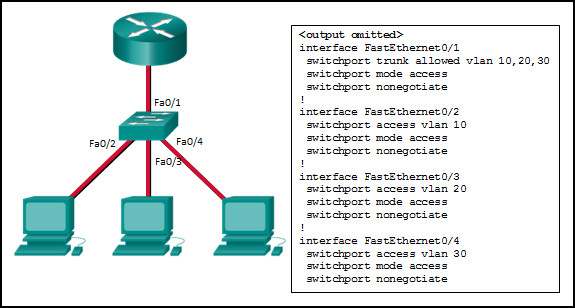
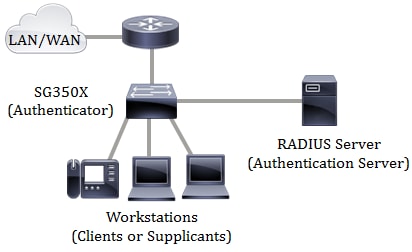
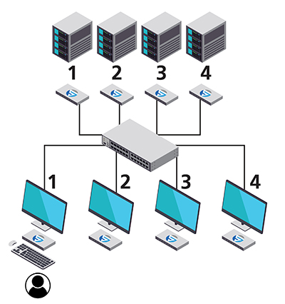
41 you have installed a new switch with connected workstations as shown in the diagram
A. Connect battery lead wire to battery. B. Disconnect the black battery leadwire from the switch and connect it directly to the black brush lead. C. Disconnect the red battery leadwire from the switch and touch it directly to the red brush lead. C-1. If motor does run, proceed to Step 3. C-2. If motor does not run, a problem exists in the ... Your task in this lab is to create the following VLANs and assign port membership as follows: VLAN Name Port Membership 1 n/a FastEthernet 0/1 FastEthernet 0/2 FastEthernet 0/3 7 Accounting FastEthernet 0/4 FastEthernet 0/5 9 Research FastEthernet 0/6 FastEthernet 0/7 12 Unused FastEthernet0/8 to FastEthernet0/24 GigabitEthernet 0/1 ...
You would like to use VLANS to create workgroups based on job function. In this lab, your task is to complete the following: • Create the following VLANs and assign port membership as follows: VLAN Name Port Membership FastEthernet 0/1 FastEthernet 0/2
You have installed a new switch with connected workstations as shown in the diagram
Before putting a new switch into operation on your network, read the vendor's documentation carefully and make sure that you understand how things work. Some vendors may not enable spanning tree as a default on all ports. Other vendors may implement special features or vendor-specific versions of spanning tree. Secure the new switch to the jet pump or install on the piping of the existing submersible well pump system. Use teflon tape on the pressure switch inlet to prevent leaks. Click here to see video How to Apply Teflon Tape the RIGHT Way; Remove the cover of the new pressure switch with pliers and set aside. A wiring diagram is normally found on ... chapter 0. You have been hired as a network technician for a small corporate network. Today is your first day on the job, and you need to familiarize yourself with the network. Add the monitor to the office next to the computer. Use the DVI-D cable to connect the monitor to the computer.
You have installed a new switch with connected workstations as shown in the diagram. The diagram shows an electrical circuit. (a) The 6 V battery shown in the diagram is made up of a number of identical 1.5 V cells. Calculate the minimum number of cells needed to make the battery. _____ Number of cells =_____ (1) (b) The switch in the diagram is shown in the open position. Closing the switch completes the circuit. Connect the new socket or switch as shown in the appropriate wiring diagram in these fitting instructions taking care that only the copper conductor(s) enter the terminals. It is absolutely vital that the terminal screws do not clamp on the insulation of the cables. You have installed a new switch with connected workstations as shown in the diagram. You would like to use VLANs to create workgroups based on job... p. Bldg2(config-vlan)# name Unused q. Bldg2(config-vlan)# interface range fa0/8 - 24, gi0/1 - 2 r. Bldg2(config-if-range)# switchport access vlan 12 s. CTRL + Z 3. Bldg2# copy run start 4. Press Enter, Press Enter In this lab, you will explore how VLAN membership affects device communications. The LAN is configured as shown in the diagram, with all switch ports up and assigned to the ...
An electrical wiring diagram can be as simple as a diagram showing how to install a new switch in your hallway, or as complex as the complete electrical blueprint for your new home or home improvement project. Lighting For The Home. Lighting Electrical Codes. wiring a switch Wiring a Light Switch - Diagram 1 Cisco 715 lab you have installed a new switch with connected workstations as shown in the diagram. You will need to separate the red wires as indicated on the piggyback instructions and connect them properly to position 2 and position p2 on the new switch. If you are going to install a new one then go for three wire control methods. As you see in the 2 way switch diagram below, you will find that the phase/live is connected with the common of the first 2-way switch. PIN1 & PIN2 of the first switch are connected with the PIN1 & PIN2 of the second switch respectively. • Connect the wire identified as Common/Hot in Step 1 to HOT. • Connect one of the other wires to 1-POLE. • Connect remaining wire to 3-WAY. NOTE - In a 3-Way installation, use one dimmer and one switch. Do NOT use two dimmers. NOTE - If you have purchased an adorne Locator Light or Accent Nightlight, please refer to those instructions at ...
4. Locate and remove the 4th gear pressure switch from the valve body housing and install the new 4th gear switch. See Figures 1 & 2. Figure 1 Figure 2 5. Next, install the new torque converter clutch solenoid using the new studs and the included shouldered nuts. Torque both the studs into the case and The white neural wire in this new /3 cable won't connect to anything, will just be capped off, and is required by code in case someone replaces your new switch with a smart switch that needs neutral. This isn't a lot more work than your original plan of running a cable from the switch to the new ceiling light box. SWITCHES on an installed switch. See Figure 6. Note: You must use the same group of trunk ports on each switch throughout the system. However, cables can be connected to any port in the group. For example: If TO DISH port numbers c through e are connected on the first switch, you must connect all switches together using ports c through e. You have been assigned to manage a small branch office as shown in the network diagram. You have connected all devices. You now need to configure the hostname and interface descriptions on the Cisco switch. Complete the following tasks: Set the hostname on the switch to the name indicated in the diagram (Branch1).
You have been assigned to manage a small branch office as shown in the network diagram. You have connected all devices. You now need to configure the hostname and interface descriptions on the Cisco switch. Complete the following tasks: Set the hostname on the switch to the name indicated in the diagram (Branch1).
Forward the frame out all ports except Fa0/1. It will not record the location of any device. You have a switch connected to a small network as shown in the Exhibit. A hub connects Wrk1 and Wrk5 to the switch. The switch has the following information in its CAM table: Fa0/1 Wrk1/Wrk5. Fa0/2 --. Fa0/3 Wrk3. Fa0/4 --.
switch. If there are 2 wires connected to two screw terminals (not including a green or bare copper wire used for grounding), you have a Single-Pole switch. 3-Way: Look at the back of your switch. If there are 3 wires connected to three screw terminals (not including a green or bare copper wire used for grounding), you have a 3-Way switch.
For example, we have power supplies with 1 Amp, 3 Amp, 5 Amp, 10 Amp, and 20 Amp output current. The more devices we have, the more current we need and the bigger the power supply gets. So this was an in-depth overview of the essential industrial electrical panel components that you see in a panel. This article was brought to you by RealPars in ...
Last day i am doing some new electrical instillation, and i saw the handle type manual changeover switch, and get a photo for you, which help you in understanding the connection. Note this post is only about handle type manual changeover switch wiring diagram , however the knob type changeover connection is also same.
This will allow the workstation to connect to the local network (as shown in the Exhibits) and another small network, which is not yet built or connected. Complete this lab as follows: In the notification area, right-click the networking icon and click Open Network and Sharing Center.
Bldg2>enable Bldg2#configure terminal Bldg2(config)#vlan 7 Bldg2(config-vlan)#name Accounting Bldg2(config-vlan)#interface range fa0/4 - 5 Bldg2(config-if-range)#switchport access vlan 7 (Press Ctrl + Z) Use similar commands to create additional VLANs and assign members. When you are finished, use the copy run start command in EXEC mode to save the changes.
When you are finished use the copy run start command in exec mode to save the changes. You would like to use vlans to create workgroups based on job function.
This page is dedicated to Wiring Diagrams that can hopefully get you through a difficult wiring task or just to learn some basics in how to wire a 2-way switch, 3-way switch, 4-way switch, outlet or entertainment component diagrams.If you don't see a wiring diagram you are looking for on this page, then check out my Sitemap page for more information you may find helpful.
A user has installed a new wireless printer on the network. ... You have been asked to connect three 802.11a devices to an 802.11g access point that is configured with WEP. ... troubleshooting a workstation in the office and determined that it is an issue with the cabling somewhere between the workstation and the switch. You have tested the ...
Transcribed image text: Change Location plied Lab have installed a new switch with mnected workstations as shown in e diagram. You would like to use ANs to create workgroups based on b function. Your task in this lab is to eate the following VLANs and assign ort membership as follows: WLAN Name na Port Membership FastEthernet0/1 FastEthernet 0/2 FastEthernet 0/3 FastEthernet0/4 Wik2 192.150 ...
chapter 0. You have been hired as a network technician for a small corporate network. Today is your first day on the job, and you need to familiarize yourself with the network. Add the monitor to the office next to the computer. Use the DVI-D cable to connect the monitor to the computer.
Secure the new switch to the jet pump or install on the piping of the existing submersible well pump system. Use teflon tape on the pressure switch inlet to prevent leaks. Click here to see video How to Apply Teflon Tape the RIGHT Way; Remove the cover of the new pressure switch with pliers and set aside. A wiring diagram is normally found on ...
Before putting a new switch into operation on your network, read the vendor's documentation carefully and make sure that you understand how things work. Some vendors may not enable spanning tree as a default on all ports. Other vendors may implement special features or vendor-specific versions of spanning tree.













0 Response to "41 you have installed a new switch with connected workstations as shown in the diagram"
Post a Comment