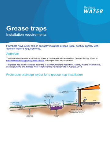
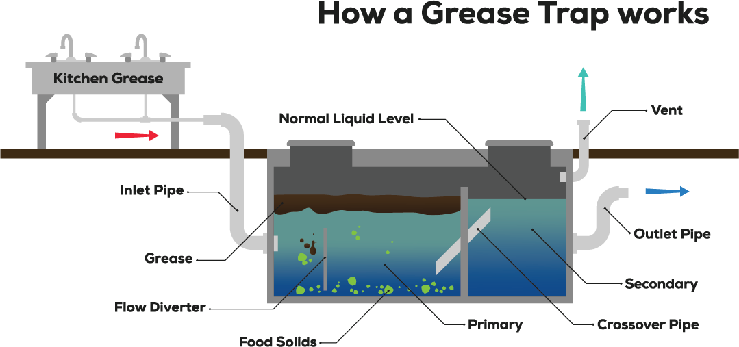
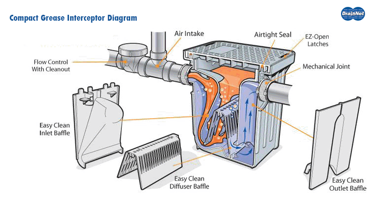
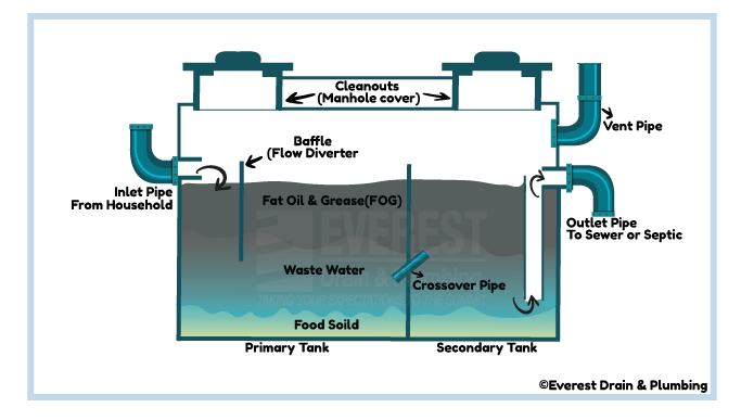
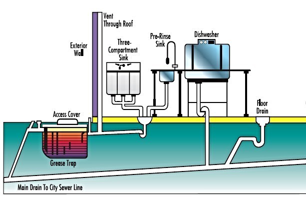
41 grease trap piping diagram
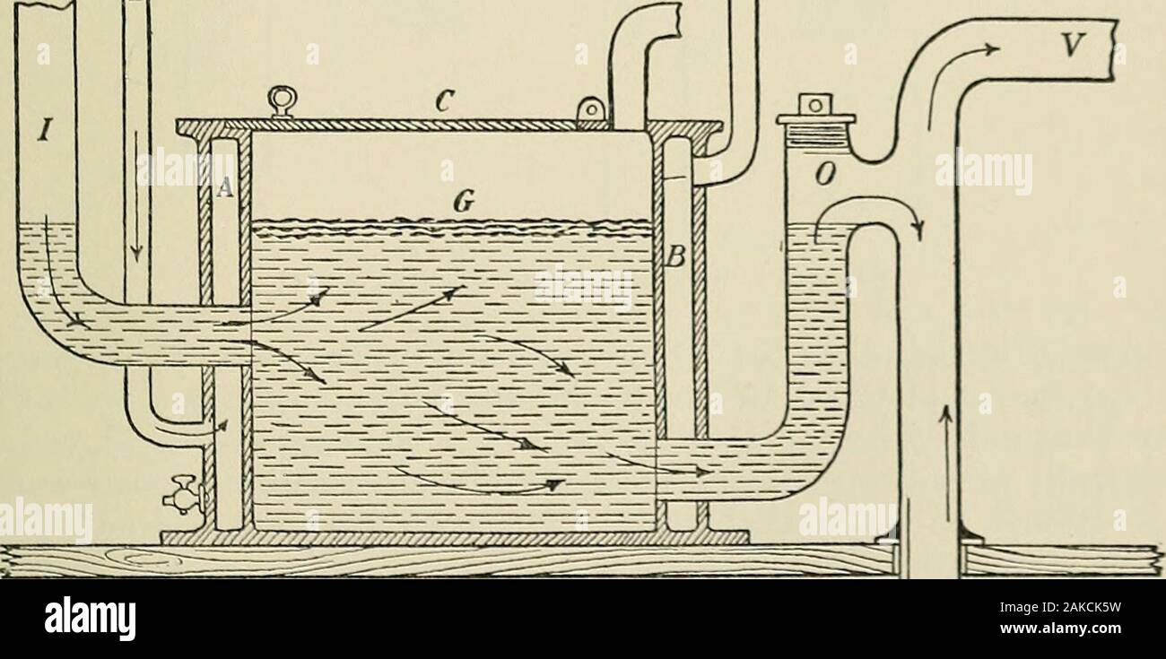
The International Plumbing Code (IPC) 1002.1 (exception 3) allows a grease interceptor to serve as a fixture trap - where it is intended by the manufacturer to serve as a trap - for a single fixture or a combination sink of not more than three compartments so long as the vertical distance from the outlet of the fixture to the inlet of the interceptor is not more than 30 inches and the ... and similar equipment and to prevent grease accumulations from clogging connecting piping and sewer lines. In 1883, one Nathaniel T. Whiting of California applied for a patent on a grease trap, which was issued in October of 1884. Whiting's design principle was not unlike that of present day grease interceptors.
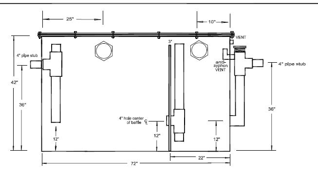
XL Grease Trap 75 GPM - CAD Drawing 1. XL Grease Trap 75 GPM - CAD Drawing 2 - In Ground Installation. XL Grease Trap 75 GPM - CAD Drawing 3. XL Grease Trap 75 GPM - CAD Drawing 4 - Not Traffic Rated. XL Grease Trap 75 GPM - CAD Drawing 5 - In- Ground Installation M-Rated Cover.

Grease trap piping diagram
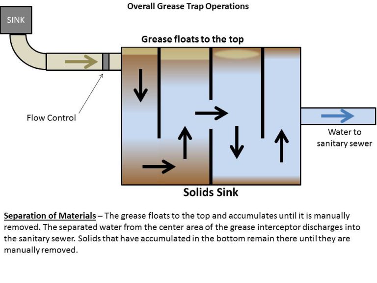
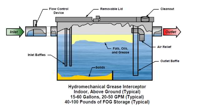
Diagram A OPERATION OF GREASE INTERCEPTORS SIZING The Plumbing and Drainage Institute (PDI) as well as some national and local codes have recognized different ways of sizing grease interceptors. It is advisable to check with local authorities for sizing requirements in your particular locality. Grease Separators G Series G-C Series GF Series RTO Series GIS Series Grease Separator Sizing Installation Diagrams Grease Separator Cleaning Rep Search Contact Us Protect waste lines against blocking and stoppages. Select a separator with a gallon-per-minute flow equal to the initial tank discharge capacity. Draw-off valve available. With an internal flow control, an external […] Grease Trap/Grease Interceptor A grease trap/grease interceptor is the device utilized to effect the separation of grease and oils in wastewater effluents from food service establishments. Such traps or interceptors may be of the "outdoor" or below ground type normally referred to as large grease interceptors, or the "under-the-counter" package ...
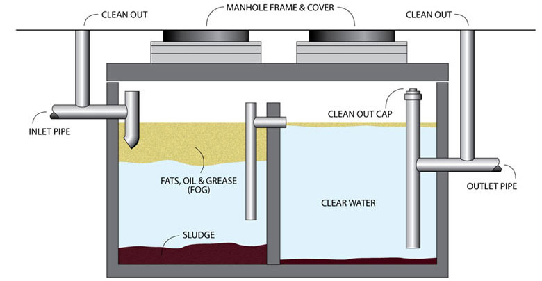
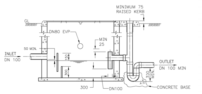
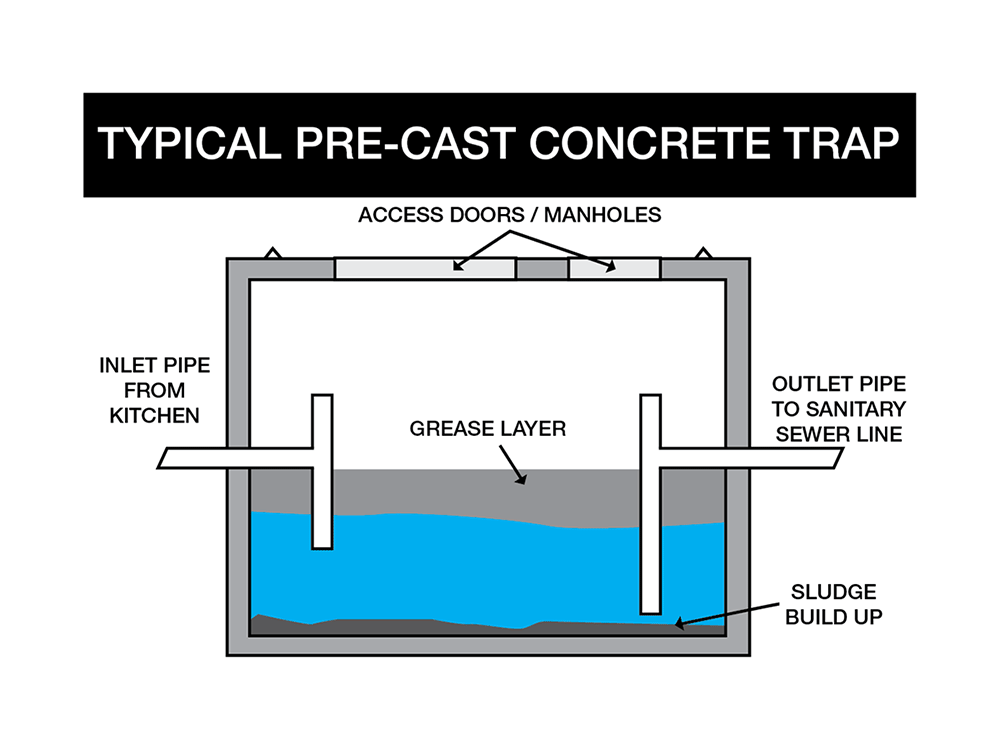
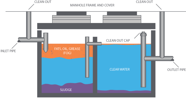
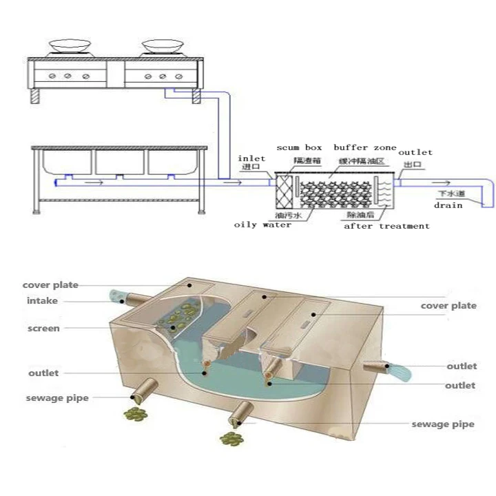
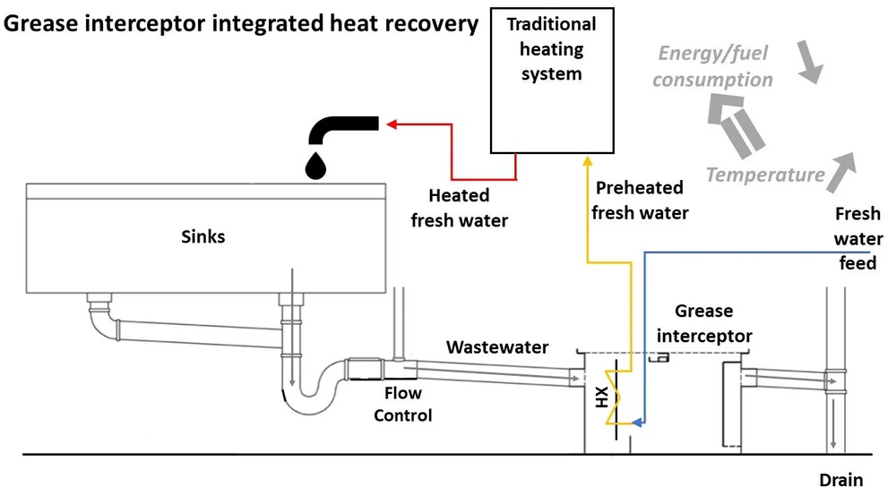
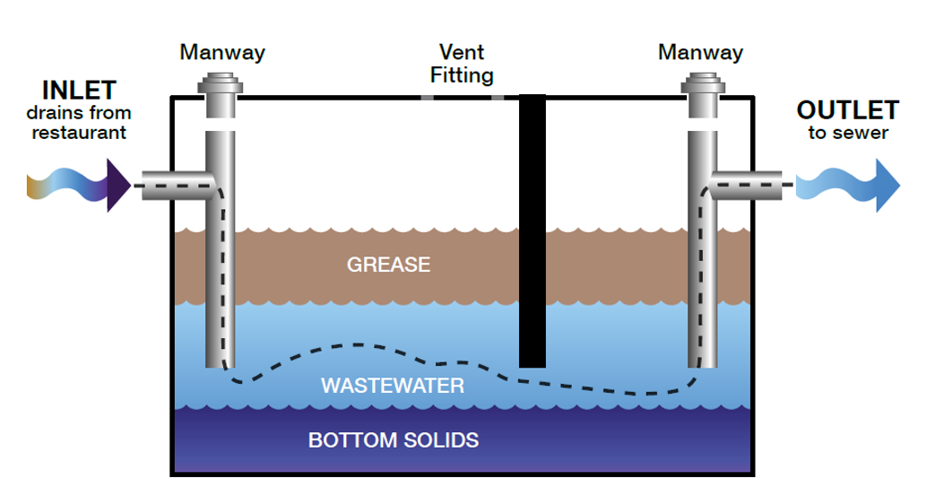
Grease trap piping diagram. Nov 08, 2019 · Drain Piping Pitch(Slope) – In plumbing the grade at which the drain piping is installed to assure that the waste water flows at a speed that allows the piping to be self scouring. Meaning the turbulence and movement of the water cleans the inside of the pipe. 1/4″ per foot is a common pitch for plumbing. Piping or tubing is usually inserted into fittings to make connections. Connectors are assigned a gender, abbreviated M or F. An example of this is a "3 ⁄ 4-inch female adapter NPT", which would have a corresponding male connection of the same size and thread standard (in this case also NPT). Grease Interceptor Sizing and Installation Guidelines E-102 Grease protection is an essential element for restaurants, cafes, catering facilities, commissaries, hotels, cafeterias, convenience stores, full service grocery stores, schools, hospitals, and food manufacturing plants. Grease traps usually consist of an underground, watertight, concrete tank with baffled inlet and outlet piping. The outlet pipe has a tee that allows the internal discharge to be located within 0.3 m of the tank bottom. The size of the grease trap depends on the anticipated flow rate, water temperature, and grease concentration.
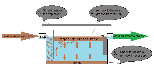
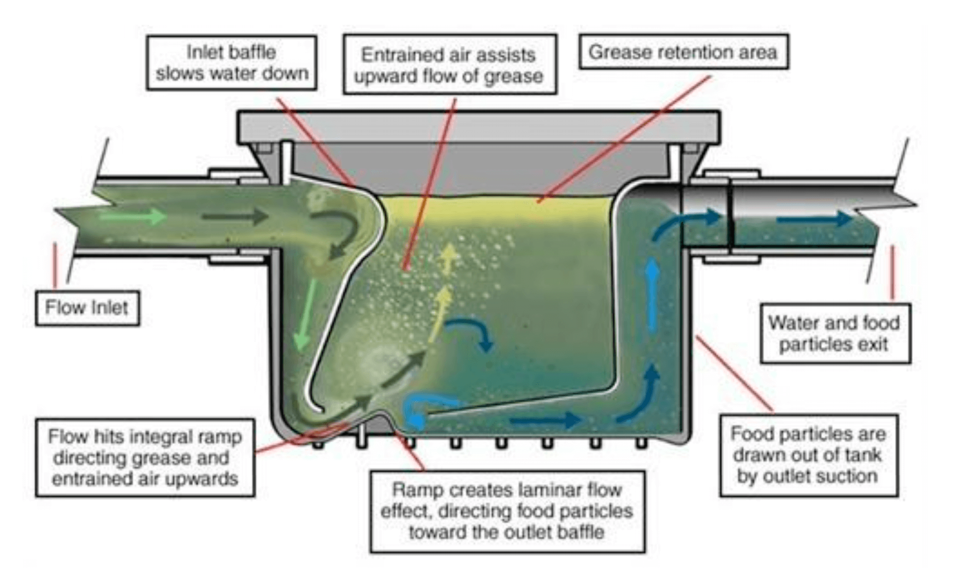
In the most basic terms, a grease trap works by slowing down the flow of warm/hot greasy water and allowing it to cool. As the water cools, the grease and oil in the water separate out and float to the top of the trap. The cooler water - minus the grease - continues to flow down the pipe to the sewer. There are two primary methods that grease ... Nathaniel Whiting was the first person to obtain a patent for a grease trap. Grease traps are usually constructed from stainless steel or plastic and must be cleaned occasionally. How To Install A Residential Grease Trap. Unless you lack basic skills, grease trap installation doesn't require the services of a professional plumber. Indirect waste piping (without traps) Comm 81.01 (113) g. Indirect waste piping (with traps) Comm 82.33(5) h. Waste sink installation Comm 82.33(8)(a) i. Grease interceptor drains flowing to Comm 82.34(5)(d)7. j. Restaurant sinks (scullery) See Chapter M in this manual. k. Hand sinks (Health Depart. Requirements) See Chapter M in this manual. grease waste piping center line piping legend miscellaneous p = san, vent stack or domestic water riser st = storm drain leader riser f = fire standpipe riser equipment designation detail designation sheet note number revision number plumbing legend and abbreviations riser no. riser equipment equipment no. dwg. sheet no. detail number p 1 cp 1 ...
Part I: Guidance for Grease Trap Sizing and Design Criteria A. Introduction The City of Carrollton requires grease traps or interceptors in commercial food establishments to prevent the entry of grease, fats, oils and debris into the city's sanitary sewer system. These substances cause sewer back-ups, blockages, and sanitary sewer overflows. Grease traps also known as grease interceptors are plumbing systems that serve as our first line of defense when it comes to preventing fats, oil and grease (FOG) from entering the water waste management system and eventually the ocean. A grease trap, which is usually made of hard plastic, fiberglass or concrete and placed inside the kitchen or ... INTERCEPTORS S-WD-INTER-5 0812 GREASE INTERCEPTORS Pipe Connection No Hub (Standard) - Butt connection using no hub or neoprene coupling, suitable for cast iron, plastic, and most other piping applications. Threaded (T) - Female IPS threaded connections. Commonly Specified Options • All piping inside the grease interceptor must be PVC Schedule 40. • Procedures or physical measures must be in place to make evidence of tampering or unauthorized use immediately apparent to the GI owner/representative. ... ReWaFOG-2015_Grease Interceptor Diagram
the grease and water layers downward toward the bottom of the interceptor (Diagram E). If pressure continues to build, grease would eventually be forced under the baffle plate and out of the unit. The presence of a vented flow control device and air relief by-pass is a key element in the efficient operation of a grease interceptor. If one
piping in the grease trap should be sufficient to allow gravity-differential separation to the grease so that it will not escape hrough t e ou tle. The minimu horizontal distance shall be twenty-four inches. M104.12 Access/Covers 04.12.1 Access from the top of the grease trap shall be
Apr 30, 2021 · Trap seal is the maximum vertical depth of liquid that a trap will retain measured from the crown weir and the top of the dip of the trap. The most common of all plumbing traps is the p-trap. This is used with kitchen sinks, lavatories, and laundry sinks. Check out the diagram in Figure #1. Figure #1 Tubular P-Trap. Plumbing Codes Restrictions
Each compartment, 18 inches by 18 inches by 8 inches with 1.5-inch sink drain and trap. Vegetable prep sink, 18 inches by 18 inches by 6 inches, 1.5-inch trap and 1.5-GPM faucet. Wash sink with one set of faucets. Mop basin, 24 inches by 24 inches by 6 inches, 2-inch trap, faucet at 5-GPM max. Other.
4. Grease traps must be installed in the plumbing system for restaurants and businesses that prepare food. The location and size of the grease interceptors must be included on the isometric drawing. For further information see the Building Inspections handout titled Grease Interceptors in Kitchens. 5.
Piping Connections All Endura Grease Interceptors are manufactured with no hub connections. Standard mechanical joint couplings can be used to connect the grease interceptor to a metal or plastic piping system. If the piping system needs tobe resized, use appropriate mechanical joint reducers, but do notdecrease pipe diameter across the unit.
ASME #A112.14.3 and CSA B481.1 grease interceptor standards and greatly exceed requirements for grease separation and storage. They are compliant to the Uniform Plumbing Code, the National Standard Plumbing Code, the National Plumbing Code of Canada, and the International Plumbing Code. SPECIFICATIONS Inlet A A 35" 12-7/16" 13-3/4" 23" 5" 8-3/4 ...
• The plumbing code does not prohibit discharge of a food waste disposer downstream of the interceptor. • Mixed reviews on this: - Studies have indicated that dishwasher prerinse sinks are a significant source of grease and food waste grinders are often installed with the prerinse sink - Since a food waste grinder operates best with a cold
A grease trap is designed to prevent greasy substances from entering plumbing systems, septic tanks, and waste water treatment facilities where they are difficult to process and may create a number of environmental problems.
We stand behind the quality of our products and will make things right if you are not satisfied. All products sold from Drain-Net have a 1 year limited warranty from date of purchase against defects in material or workmanship, under normal use.
The definition of a grease trap is " a trap in a drain or waste pipe to prevent grease from passing into a sanitary sewer lines and system." A grease trap/grease inceptor is in simple terms a plumbing fixture that contains decomposing food waste, bettering the sewer system. There are three main types of grease traps:
The very first Great Basin™ grease interceptor was installed in 2006, forging a new category in the world of grease interceptors. Prior to 2006, it was undersized steel grease traps inside of the building and oversized concrete grease interceptors outside of the building. These products offered little-to-no information in the way of performance.
A grease trap is a simple device that is designed to trap oils, fats, and wax in a container to prevent them from reaching the sewers and the drainage systems. Laws in most states, especially in restaurants and food preparation businesses, mandate the installation of a grease trap.
A grease trap is designed to prevent greasy substances from entering wastewater treatment facilities, septic tanks, and plumbing systems. Greasy substances may also be a hazard to the environment. The combination of kitchen appliances attached to the grease trap determines required size.
The leach field or drain field acts as the “secondary treatment” process of the septic system that consists of underground trenches and perforated piping. The wastewater flows from the septic tank to the leach field where the partially treated wastewater enters the leach field system and filters (percolates) down though the soil for final ...
and similar equipment and to prevent grease accumulations from clogging connecting piping and sewer lines. In 1883, one Nathaniel T. Whiting of California applied for a patent on a grease trap, which was issued in October of 1884. Whiting's design principle was not unlike that of present day grease interceptors.
Steam is water in the gas phase. This may occur due to evaporation or due to boiling, where heat is applied until water reaches the enthalpy of vaporization.Steam that is saturated or superheated is invisible; however, "steam" often refers to wet steam, the visible mist or aerosol of water droplets formed as water vapour condenses.
Grease Trap/Grease Interceptor A grease trap/grease interceptor is the device utilized to effect the separation of grease and oils in wastewater effluents from food service establishments. Such traps or interceptors may be of the "outdoor" or below ground type normally referred to as large grease interceptors, or the "under-the-counter" package ...
Grease Separators G Series G-C Series GF Series RTO Series GIS Series Grease Separator Sizing Installation Diagrams Grease Separator Cleaning Rep Search Contact Us Protect waste lines against blocking and stoppages. Select a separator with a gallon-per-minute flow equal to the initial tank discharge capacity. Draw-off valve available. With an internal flow control, an external […]
Diagram A OPERATION OF GREASE INTERCEPTORS SIZING The Plumbing and Drainage Institute (PDI) as well as some national and local codes have recognized different ways of sizing grease interceptors. It is advisable to check with local authorities for sizing requirements in your particular locality.















0 Response to "41 grease trap piping diagram"
Post a Comment