41 calamp gps wiring diagram
LED might continue to blink as it has not received a GPS Fix. Once the GPS unit is located outside the Green LED should stop blinking and go solid indicating that is has acquired a GPS Fix. Installation of this device should only be done by a qualified Technician, failure to do so may result in vehicle damage, personal injury or death.
CalampInstallationDiagram1 When the device is showing towing events, is telling us that the RED and BLACK wires are correctly installed. But the device does not know that the ignition has been turned on. The white wire is how we know the ignition status. This type of issue can be caused by the following:
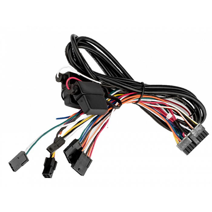
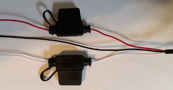
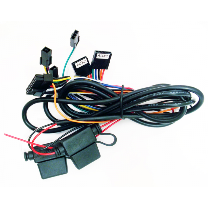
Securely attach the wiring harness to the CalAmp and find a constant 12 VDC power source. Connect the constant 12 VDC power source to the red wire on the tracking device. Next find the ignition wire on the vehicle and connect it to the ignition input in the fuse box. Finally, connect the ground wire on the harness to the vehicle ground (chassis).

Calamp gps wiring diagram
The LMU-1230 is a full-featured, GPS product designed for collateral asset protection in automobiles. The new, smaller-sized devices are equipped with CalAmp's proprietary SkySmart technology, providing customers with any required OTA (over-the-air) updates device updates, dual processor performance and standard battery backup.
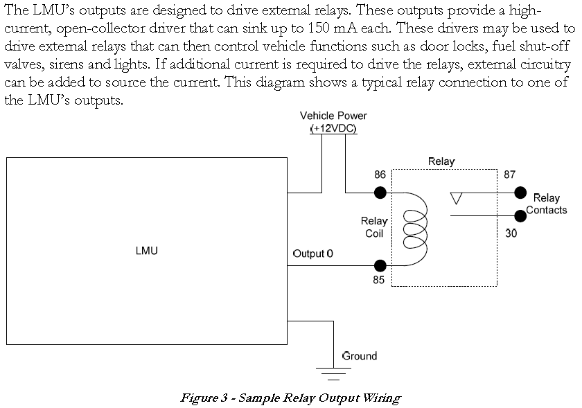
Calamp Gps Wiring Diagram – wiring diagram is a simplified enjoyable pictorial representation of an electrical circuit. It shows the components of the circuit as simplified shapes, and the faculty and signal connections surrounded by the devices.
Kahu By Spireon Came With My Truck From Fair Oaks Chrysler Dodge Jeep Ram And I M Not Happy Out Motorsports. Fair oaks chrysler dodge jeep ram installation guides sagequest calamp talon gps tracking device manualzz spireon jh01 tracker user manual standard getting started the hardware navigation systems wiring diagram enfotrace s1000 t off my car instructions for motorcycle tlt 2h b install a ...
Calamp gps wiring diagram.
Cf8c6 Calamp Gps Wiring Diagram Digital Resources Jh01 Gps Tracker User Manual Spireon Ais Gps Wiring Diagram Electricity Site Us7353034b2 Location Sharing And Tracking Using Mobile Phones Or Fl7 Installation Tutorial Video On Vimeo Ez Wiring 21 Circuit Diagram Wiring Schematic Diagram ...
The CalAmp TTU-28x0 is a motorized asset tracking and communications device that resides in private, commercial or government vehicles. The TTU-28x0 is a rugged, IP66 rated enclosure incorporating a processor, a GPS receiver, a wireless data modem and a vehicle-rated power supply.
Through the thousand pictures online about calamp gps wiring diagram, we all selects the very best series along with greatest image resolution just for you all, and now this pictures is actually one among graphics selections inside our very best images gallery regarding Calamp Gps Wiring Diagram.Lets hope you can enjoy it. That image (Calamp Wiring Diagram Calamp G1000 Installation Wiring ...
Cal Amp Wiring Diagram. by Vallery Masson on July 1, 2021. July 1, 2021 on Cal Amp Wiring Diagram. Gps security systems throughout calamp gps wiring diagram image size 504 x 720 px and to view image details please click the image. Next find the ignition wire on the vehicle and connect it to the ignition input in the fuse box.
Aviation History magazine is an authoritative, in-depth history of world aviation from its origins to the Space Age. Aviation History offers air enthusiasts the most detailed coverage of the history of manned flight, with action-packed stories and illustrations that put the reader in the cockpit with pilots and military (Army, Navy, and Marines) aviators to experience aviation’s greatest dramas.
Calamp Gps Wiring Diagram Just What’s Wiring Diagram? A wiring diagram is a kind of schematic which uses abstract photographic icons to reveal all the interconnections of components in a system. Circuitry layouts are made up of 2 points: icons that represent the parts in the circuit, as well as lines that represent the connections in between them.
Here is a picture gallery about calamp gps wiring diagram complete with the description of the image, please find the image you need. Securely attach the wiring harness to the CalAmp and find a constant 12 VDC power source. Connect the constant 12 VDC power source to the red wire on the tracking device.
Gps Tracker Wiring Diagram - wiring diagram is a simplified usual pictorial representation of an electrical circuit. It shows the components of the circuit as simplified shapes, and the capability and signal associates in the company of the devices. A wiring diagram usually gives opinion not quite the relative face and concurrence of devices ...
Diagram Calamp Gps Wiring Lmu Install Guide Dimension from calamp gps wiring diagram , source:jennylares.com So, if you like to obtain all these fantastic pics related to (Calamp Gps Wiring Diagram New), simply click save icon to download the pics in your laptop.
Vehicle Trackers. Our full-featured vehicle tracking solutions highlight vehicle tracking devices that are designed for covert installation in any vehicles for on-road tracking. Using superior internal antennas for both cellular and GPS, CalAmp's vehicle tracking devices are easy to install, economically priced while providing reliable ...
Calamp Gps Wiring Diagram Wiring Diagrams. Fleetmatics Wiring Diagram Wire Diagram. Scintillating Networkfleet Wiring Diagram Gallery Best Image. Part 5 Copper Internal Basic Wiring. Relay Connect Random 2 Calamp Gps Wiring Diagram Cinema Paradiso. Fleetmatics Wiring Diagram Unique Fleetmatics Wiring Diagram. wiringall.com:: Type 2 Wiring Diagrams.
1.3 About the CalAmp Location Messaging Unit-TTU-2830™ The CalAmp Location and Messaging Unit-TTU-2830™(TTU-2830™) is a mobile device that resides in private, commercial or government vehicles. The TTU-2830™is a single box enclosure incorporating a processor, a GPS receiver, a wireless data modem, and a vehicle-rated power supply.
Calamp Gps Wiring Diagram from hrdiagram.dominique-tiberi.fr Print the electrical wiring diagram off and use highlighters to be able to trace the signal. When you make use of your finger or perhaps follow the circuit along with your eyes, it’s easy to mistrace the circuit. 1 trick that I use is to printing the same wiring diagram off twice.
Securely attach the wiring harness to the CalAmp and find a constant 12 VDC power source. Connect the constant 12 VDC power source to the red wire on the tracking device. Next find the ignitino wire on the vehicle and connect it to the ignition input in the fuse box. Finally, connect the ground wire on the ar ness t o hev i cle gr u d ( assis).
Wk2_Submission.ipynb. GitHub Gist: instantly share code, notes, and snippets.
Description : Calamp Gps Wiring Diagram For Garmin 400 500 - Wiring Diagram throughout Calamp Gps Wiring Diagram, image size 1024 X 606 px. Truly, we also have been noticed that calamp gps wiring diagram is being one of the most popular topic at this time. So we attempted to obtain some good calamp gps wiring diagram graphic for your needs.
Securely attach the wiring harness to the CalAmp and find a constant 12 VDC power source. Connect the constant 12 VDC power source to the red wire on the tracking device. Next find the ignition wire on the vehicle and connect it to the ignition input in the fuse box. Finally, connect the ground wire on the harness to the vehicle ground (chassis).
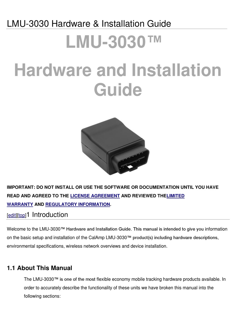
CalAmp | LMU-30xx/CVF-3030 & OBD-II Extender Cable Install Guide MBUD-0268v1.4 Page 3 3 LMU-30XX/CVF-3030 & OBD-II EXTENDER CABLE OVERVIEW The LMU-30xx/CVF-3030 features a small size, superior GPS design, OBD-II interface, and a 3-axis accelerometer. These features enable the LMU-30xx/CVF-3030 to access vehicle diagnostic interface
GPS tracking devices will not tolerate exposure to water and other liquids. (Note: The CalAmp 2830 and others are designed to be water resistant and are recommended for harsh environments.) Contact GTS if ruggedized hardware is needed. 3. CONNECT TO POWER (1) RED wire to a positive voltage of 9 - 32 Volts DC. (2) BLACK wire to ground.
Calamp Gps Wiring Diagram. By Margaret Byrd | April 8, 2020. 0 Comment. To begin installation place the vehicle tracking device under dashboard prevent unit from moving or falling it is r 2640g lmu2640 gprs user manual apv guide rev1 calamp recent posts pages archive archived vendor guides sagequest sq 2600 10 20 digital input garmin and dr id add ttu 1210 agile access genx 5p 200g lmu 200 ...
CalAmp | LMU-26xx Install Guide MBUD-0199v4.0 Page 3 3 LMU-26XX OVERVIEW The CalAmp LMU-26xx is an integrated Cellular/GPS communications device for use in-vehicle tracking. It provides communications for vehicle position and operating information as part of an overall vehicle tracking solution. It is installed within the vehicle in order to ...
4530law vehicle tracking device user manual calamp calamp gps wiring diagram fleetmatics wiring diagram sample calamp gps wiring diagram new 3030cbt location messaging unit user manual ii calamp calamp gps wiring diagram new mobile equipment manager pedigree technologies archive calamp install guide - nibc & corcra support 4230hbt vehicle tracking unit with gps gsm gprs hspa and bluetooth ...
Calamp Lmu Gps Wiring Diagram . Calamp Lmu Gps Wiring Diagram Awesome. 3030gbt Vehicle Tracking Unit with Gps Gsm Gprs and Bluetooth User. 3030cbt Location Messaging Unit User Manual Configuration App Note. Cal Amp Wiring
On this website we recommend many pictures abaout Calamp Gps Wiring that we have collected from various sites Wiring Diagram – strategiccontentmarketing.co, and of course what we recommend is the most excellent of picture for Calamp Gps Wiring.If you like the picture on our website, please do not hesitate to visit again and get inspiration from our website.
Calamp Gps Wiring Diagram : 2640g Lmu2640 Gprs User Manual Apv 2640g User Guide Rev1 Calamp : Frankie Taylor Kamis, 09 Desember 2021 We explain the benefits and pitfalls. Gps devices are among the hottest technology products, but it's easy to spend a lot on one and be disappointed. Learning to read and use wiring diagrams makes any of these ...
Generally, GPS tracking devices will not tolerate exposure to water and other liquids. The CalAmp TTU 2830 is designed to be water resistant (IP66 and IP67 rated) and is recommended for harsh environments. For environment installations where water contact can occur, we recommend adding silicone to the device seal. Do
Find your calamp gps wiring diagram here for calamp gps wiring diagram and you can print out. Search for calamp gps wiring diagram here and subscribe to this site calamp gps wiring diagram read more!
We'd love to chat. Please fill out the form below and a member of our team will be in touch soon
30.9.2021 · N. Korea's parliamentary session. This photo, released by North Korea's official Korean Central News Agency on Sept. 30, 2021, shows Kim Song-nam, director of the International Department of the ruling Workers' Party's Central Committee, who was elected as a member of the State Affairs Commission, the country's highest decision-making body, during …

Sensor level bahan bakar ultrasonik nirkabel dengan 4g,perangkat pelacak gps truk sensor level oli sistem pemantauan bahan bakar - buy sensor bahan bakar gps untuk tugas berat truk ble cair tingkat ...

En labs 2.5 "3.5" ide hdd untuk sata converter adapte kartu ide 40pin /44pin hard drive disk dvd burner untuk sata papan utama







0 Response to "41 calamp gps wiring diagram"
Post a Comment