40 free body diagram of pendulum
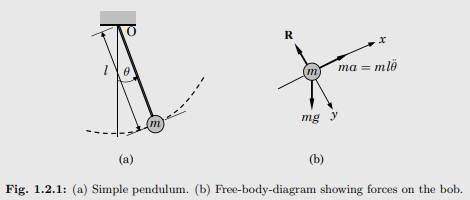
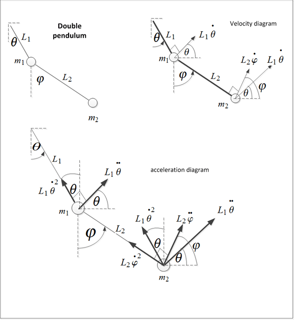
A pendulum is a device that is found in wall clocks. It consists of a weight (bob) suspended from a pivot by a string or a very light rod so that it can swing freely. When displaced to an initial angle and released, the pendulum will swing back and forth with a periodic motion. By applying Newton's second law of motion for rotational systems ... Single and Double plane pendulum Gabriela Gonz´alez 1 Introduction We will write down equations of motion for a single and a double plane pendulum, following Newton's equations, and using Lagrange's equations. Figure 1: A simple plane pendulum (left) and a double pendulum (right). Also shown are free body diagrams for the forces on each mass.
Answer to 1. Draw a free body diagram of a pendulum while in. This problem has been solved! See the answer See the answer See the answer done loading

Free body diagram of pendulum
Check here to show the free-body diagram Purple is the true motion; orange is the comparison motion. This is a simulation of a simple pendulum (a ball attached to a massless rod). If the damping is set to zero, the pendulum moves without resistance. The larger the damping, the larger the resistive torque. Free body diagram of pendulum Thread starter-EquinoX-Start date Nov 30, 2008; Nov 30, 2008 #1 -EquinoX-564 1. Homework Statement I am asked to draw a free body diagram of a pendulum and a bob with it's maximum amplitude of 30 degrees. Below is my attempt, I just forgot to say that theta is equal to The pendulum is pivoted about one end and released from rest from and angle of 0. (angle with the vertical). (a) Find the distance, dcm, of center of mass of this pendulum from its pivot. (6) Draw a free body diagram and write down Newton's 2nd Law (for rotation) for the pendulum at time t. (c) What is the equation of motion of the pendulum?
Free body diagram of pendulum. double pendulum problem lsu free body diagrams for the forces on each mass 2 newton's equations for the double pendulum we derive the same expressions for the first particle r. phys5 1f 10. 12 7 the simple pendulum step 1 - draw a free body diagram for the ball immediately after it is released the free body diagram is drawn in figure 12 18 ... The free body diagram depicting the torques on the body is shown below. The forces on the pendulum are the tension in the rod t and gravity. The diagram at the right shows the pendulum bob at a position to the right of its equilibrium position and midway to the point of maximum displacement. Solved 1 2 3 Draw The Free Body Diagrams For Pendulum. The free-body diagram is drawn in Figure 12.18). There is a downward force of gravity, and a force of tension directed away from the ball along the string.2 pages Double Pendulum • The disk shown in the figure rolls without slipping on a horizontal plane. Attached to the disk through a frictionless hinge is a massless pendulum of length L that carries another disk. The disk at the bottom of the pendulum cannot rotation relative to the pendulum arm. • Draw free-body diagrams and
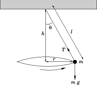
Dr. Massa and the great Orbax discuss the conical pendulum, drawing free body diagrams and centripetal acceleration. Find the equation of motion of this pendulum by taking the time rate of change of the angular momentum computed with respect to the pivot. ... Be sure to include a free body diagram. Pendulum with Torsional Spring - Solution: The free body diagram depicting the torques on the body is shown below. Note the directions of the unit moving projectile. After the capture, the pendulum swings to a maximum opening angle of µ. Using conservation of momentum and energy, the initial velocity v of the projectile can be determine based on the opening angle µ. The center of mass of the pendulum is labeled "cm". Figure 3.2: The free-body diagram for the ballistic pendulum. To begin, we first draw the free-body diagram where the forces acting on the pendulum are its weight and the reaction at the rotational joint. We also include a moment due to the friction in the joint (and the rotary potentiometer).
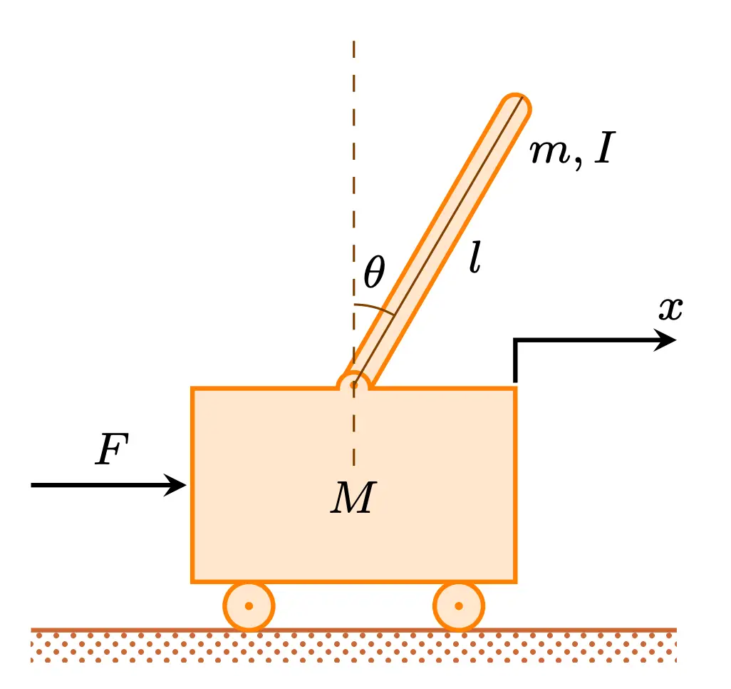
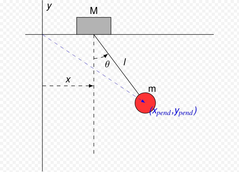
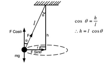
The origin is just something we make up, as is the arm length. Let's say we construct our pendulum like so: var p = new Pendulum (new PVector (100, 10), 125); We're storing the current angle on the angle property. So relative to the origin, the pendulum's position is a polar coordinate: (r,angle). And we need it to be Cartesian. Download scientific diagram | Inverted Pendulum-cart system (Free body diagram). from publication: Ant Colony based LQR and PID tuned parameters for controlling Inverted Pendulum | This paper ... The force of the gravity can be decomposed into two components; one is parallel to the pendulum or the tension, and one perpendicular [3], as shown in Fig. 1. Below are the free-body diagrams of the two elements of the inverted pendulum system. Summing the forces in the free-body diagram of the cart in the horizontal direction, you get the following equation of motion. (1) Note that you can also sum the forces in the vertical direction for the cart, but no useful information would be gained.
immediately after it is released. The free-body diagram is drawn in Figure 12.18). There is a downward force of gravity, and a force of tension.2 pages Check here to show the free-body diagram Purple is the true motion; orange is the comparison motion. This is a simulation of a simple pendulum (a ball attached to a massless rod). If the damping is set to zero, the pendulum moves without ...

Download scientific diagram | Free body diagram of the inverted pendulum Summing the forces along the horizontal direction as shown in the FBD, following equation for N was obtained: from ...
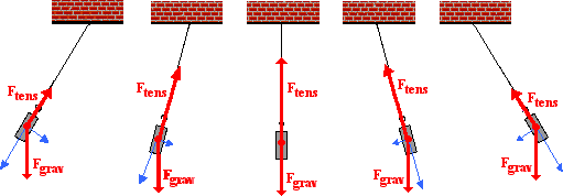
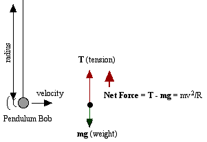
The second is tension in the string which changes in both size and direction as the pendulum swings. When it swings through the bottom of its arc, the pendulum has maximum speed and requires the maximum force to hold it in its circular path. The forces at the bottom are shown here in a free-body diagram.

Free Body Diagram of an Inverted Pendulum in TikZ. April 20, 2021 April 15, 2021 by admin. In this tutorial, we will draw a free body diagram of an inverted pendulum in LaTeX using TikZ package. We will draw a cart and place a moving rod on top of it, then place the arrows to represent forces and label our elements.
1 answerLet us consider the pendulum to be in simple harmonic motion, in this case, the restoring force, −mgsinθ − m g sin θ acting on the bob of the pendulum is ...
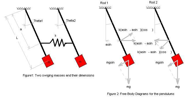
-Rigid Body Kinematics x y z = cosθ sinθ 0 −sinθ cosθ 0 0 0 1 X Y Z i j k = cosθ sinθ 0 −sinθ cosθ 0 0 0 1 I J K . Derivation of Equations of Motion -Rigid Body Kinematics Free Body Diagram After substitutions and evaluation: Derivation of Equations of Motion-Lagrange Equations ... Spring Pendulum Dynamic System Investigation ...
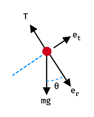
We treat the pendulum bob as a point particle. Drawing the free body diagram for the pendulum bob lets us write an expression for the net force acting on it. Define these variables: \( T = \) tension in the rod \( m = \) mass of pendulum \( g = \) gravitational constant \( b = \) damping (friction) constant \( F_d = \) damping force

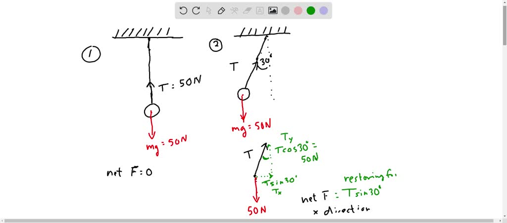
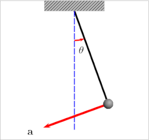
Next we draw the free body diagram for the pendulum. The forces on the pendulum are the tension in the rod T and gravity. So we can write the net force as: F = T cos θ j − T sin θ i − m g j. Using Newton's law F = m a and the pendulum acceleration we found earlier, we have.
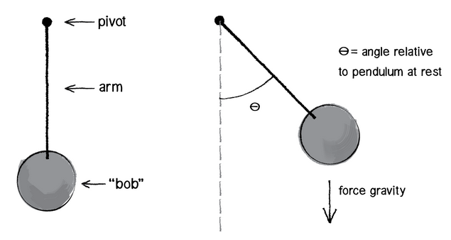
Draw a free body diagram of a pendulum which has just been released (initial angle – θ). (Hint: the gravitational force should be thought of having two ...
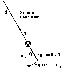
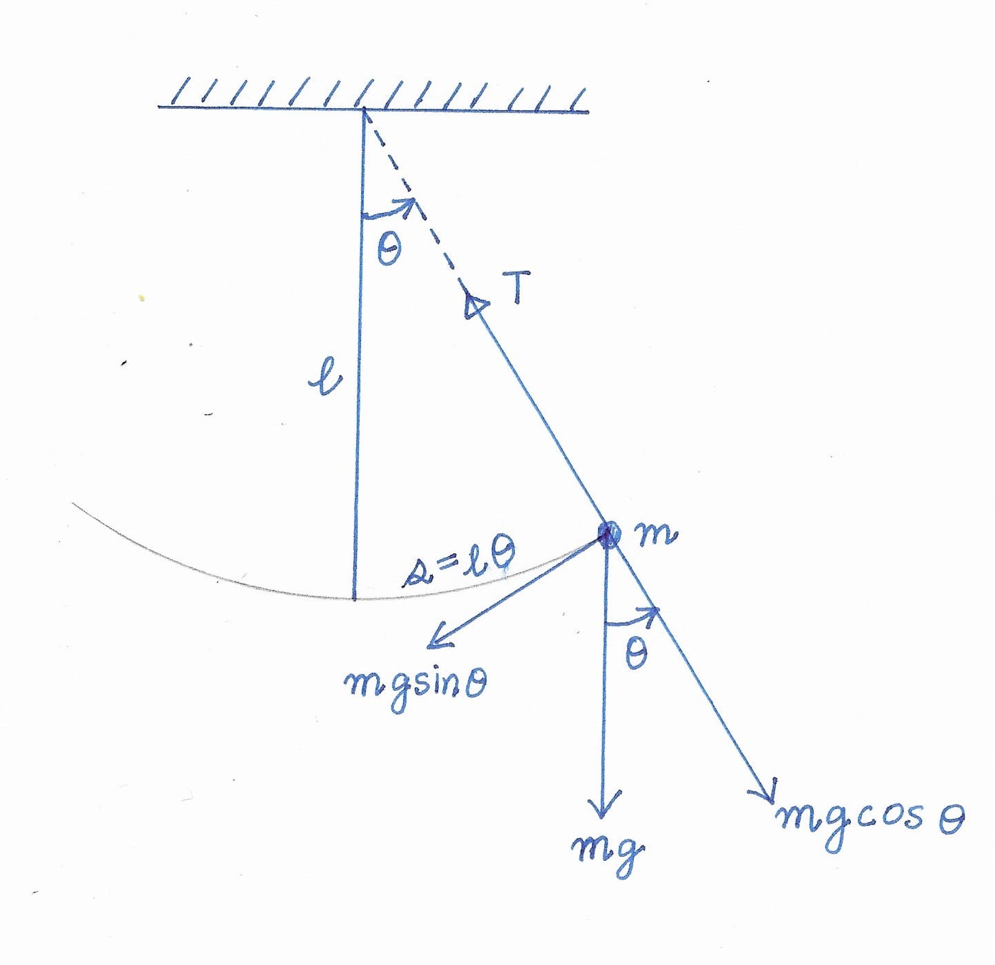
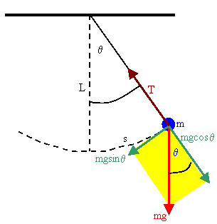
free body diagram in Fig. 6 below. Free Body Diagram Fig. 6 The free body diagram of the pendulum bob shows the gravitational force mg, the tension force T and the centripetal acceleration ac. The components of the gravitational force are also shown. Applying Newton's second law along the direction of tension force on gets T mg θ mgCos(θ)
A simple pendulum consists of a relatively massive object - known as the pendulum bob - hung by a string from a fixed support. When the bob is displaced from equilibrium and then released, it begins its back and forth vibration about its fixed equilibrium position. The motion is regular and repeating, an example of periodic motion. In this Lesson, the sinusoidal nature of pendulum motion is ...

The force diagram on the pendulum is shown in Figure 24.4. In particular, there is an unknown pivot force and the gravitational force acts at the center of mass of the rod. Figure 24.4 Free-body force diagram on rod The torque about the pivot point P is given by P τ=r P,cm ×mg. (24.3.2)
Draw free-body diagrams that conform to the assumed displacement positions and their resultant reaction forces (i.e., tension or compression). c. Apply to the free body diagrams to obtain the governing equations of motion. The matrix statement of Eqs.(3.123) is The mass matrix is diagonal, and the stiffness matrix is symmetric.

The pendulum is pivoted about one end and released from rest from and angle of 0. (angle with the vertical). (a) Find the distance, dcm, of center of mass of this pendulum from its pivot. (6) Draw a free body diagram and write down Newton's 2nd Law (for rotation) for the pendulum at time t. (c) What is the equation of motion of the pendulum?
Free body diagram of pendulum Thread starter-EquinoX-Start date Nov 30, 2008; Nov 30, 2008 #1 -EquinoX-564 1. Homework Statement I am asked to draw a free body diagram of a pendulum and a bob with it's maximum amplitude of 30 degrees. Below is my attempt, I just forgot to say that theta is equal to
Check here to show the free-body diagram Purple is the true motion; orange is the comparison motion. This is a simulation of a simple pendulum (a ball attached to a massless rod). If the damping is set to zero, the pendulum moves without resistance. The larger the damping, the larger the resistive torque.


0 Response to "40 free body diagram of pendulum"
Post a Comment