39 dimming ballast wiring diagram
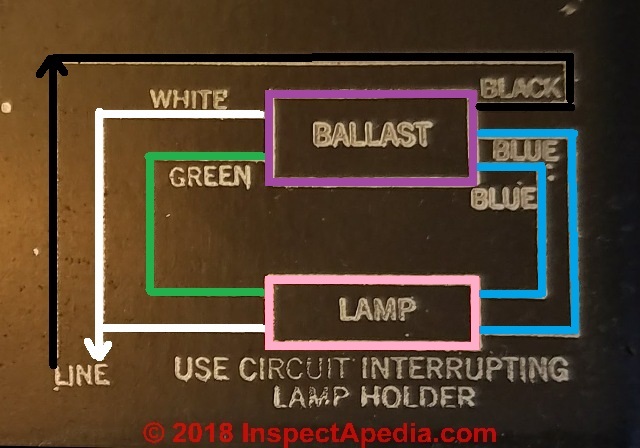
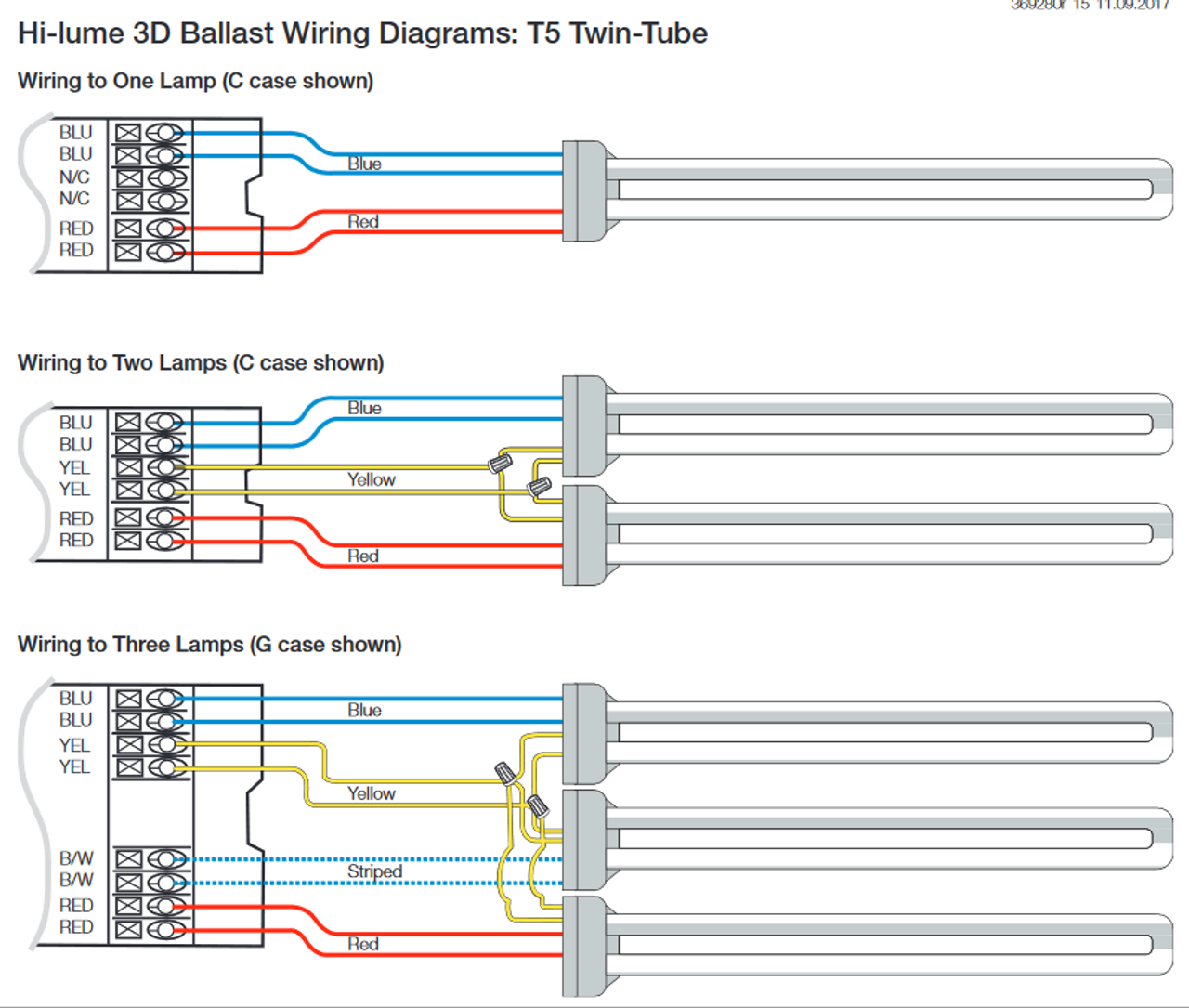
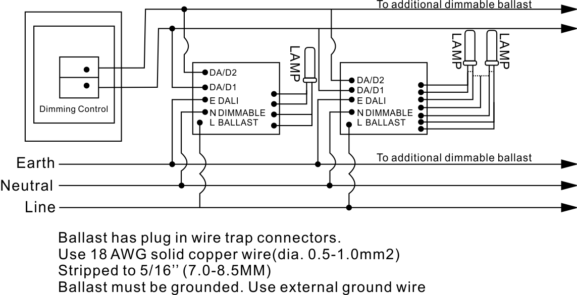
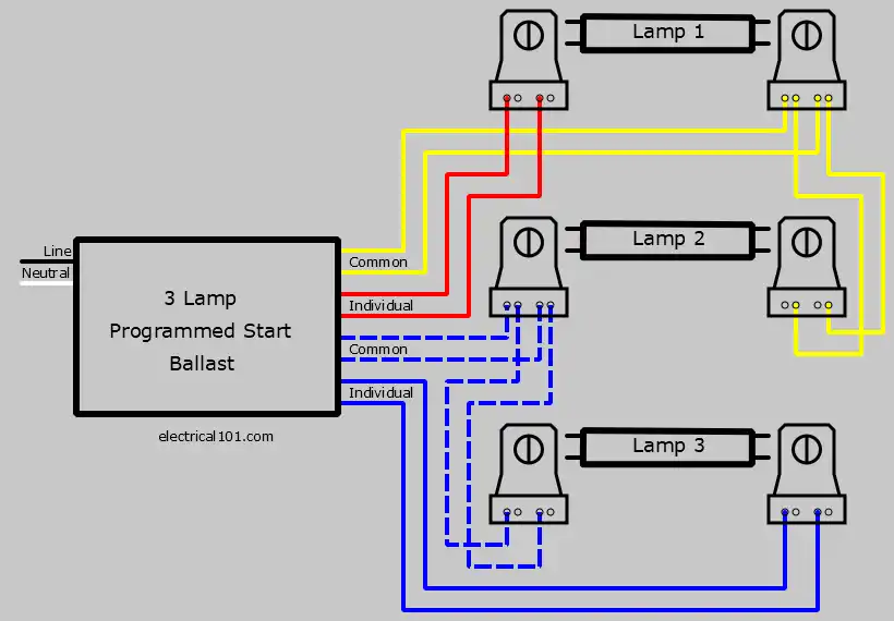
our dimming ballasts. See the wiring diagrams in the Appendix for more information. • 3-wire control Ballasts controlled by this method require three control wires:Switched Hot,Dimmed Hot,and Neutral.The Switched Hot and Neutral provide power to the ballast. The Dimmed Hot provides a line-voltage dimming signal from the control to the ballast. These ballasts are usually rapid start or programmed start, and have a good dimming range. Dimming fluorescent lights are usually found in commercial and institutional environments and not common in the household. Since dimmable fluorescent tubes are wired in series, they use non- shunted lampholders. See Rapid Start Ballast Lampholder Wiring ...
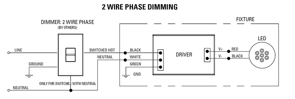
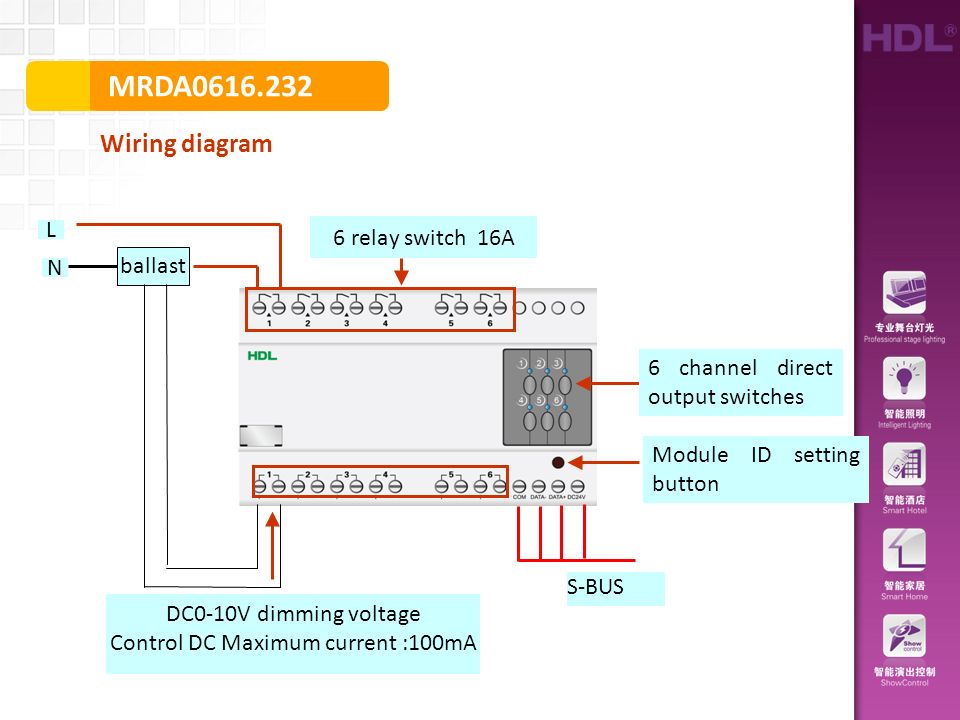
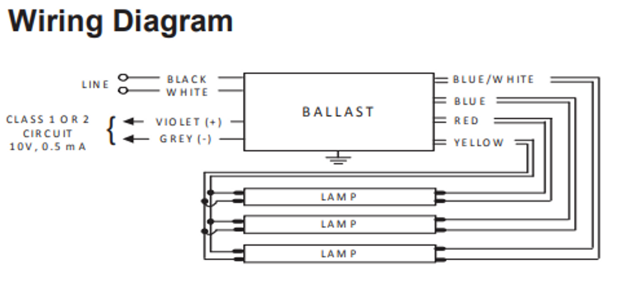
0-10V dimming wiring diagram 0-10V dimmer switch Leviton IP710-LFZ or equal For other types of dimming control systems, consult controls manufacturer for wiring instructions switched hot (black) switched hot (red typical) low voltage dimming wires (purple & gray typical) + Electrical Panel hot (black typical) 120V or 277V, 60 Hz neutral (white) ground ground-LED

Dimming ballast wiring diagram
4 T8 ballasts 7 T5 ballasts 8 CFL ballasts 9 Magnetic T12 conversion to electronic 9 Circline and signage ballasts 10 T12 ballasts 11 Controllable ballasts ... specifications, wiring diagrams, and more • Dynamic cross-reference tool — find equivalent Philips A wiring diagram is a streamlined traditional photographic representation of an electric circuit. Make sure all connections are in accordance with the national electrical code and any local regulations. Select the appropriate wiring diagram on back to connect the emergency ballast to the ac ballast and lamp s. Jan 28, 2018 · Or you are a student, or perhaps even you who just want to know concerning Lutron Dimming Ballast Wiring Diagram. Dimmable Ballast Wiring Diagram, size: 800 x 600 px, source: i0.wp.com. Whatever you are, we aim to bring the material that matches what you are trying to find. You might come from a search engine, after that discover this internet site.
Dimming ballast wiring diagram. intermittent operation of SuperDim ballasts. • Polarity of control wiring must be maintained throughout the system for proper operation (purple-to-purple and gray-to-gray). Lamp Wiring • A ballast-to-lamp wiring diagram is shown on each ballast label. These diagrams must be adhered to for proper lamp and ballast operation. Installing and Wiring an EcoSystem TM Dimming Ballast This section lists the typical workflow followed to mount and wire an EcoSystem ballast. This section also describes the procedures needed to perform each step. If you are installing a fixture that is already mounted and partially wired, you will not need to perform ... BF of Lutron dimming ballasts The ballast factor of Lutron linear fluorescent dimming ballasts is 0.85 or greater and for compact fluorescent dimming ballasts it is 0.95 or greater. See ballast specification sheet for available ballast factors for a given lamp. Selecting CBF Lutron enables customers to order ballasts with a These ballasts are usually rapid start or programmed start, and have a good dimming range. 2 Lamp Dimming Ballast Wiring Diagram. Using Advance Mark 7 or Mark 10 dimming ballast and dimmer switch. 2 lamp series ballast wiring. Often, dimming ballasts and dimming LED power supplies use V control signals to control dimming functions.
WD-904: Wiring Diagram for 10-Wire to 8-Wire Electronic Pre-Heat Rapid Start Ballasts DIMMING APPLICATION BRIEF EasyDim - Issue includes Charts and Diagrams that demonstrate the potential power savings of each optional control device at various light levels. 0 10v Dimming Ballast Wiring Diagram Download. 0 10v dimming ballast wiring diagram - Just What's Wiring Diagram? A wiring diagram is a type of schematic which makes use of abstract photographic symbols to reveal all the affiliations of components in a system. Circuitry layouts are made up of 2 things: symbols that stand for the components… Dimming Ballasts Wiring Electrical 101 ムread Pdf Epub Mark 10 Dimming Ballast Wiring Diagram Dimmer switch wiring electrical 101 how to install a 0 10 v lighting control diagram system png 1140x937px 010 waterproof blue sea 7506 deckhand 6a max forward phase dimming solutions usai light and replacement diy installing single pole customer ... Instant start ballasts can only be wired in parallel according to the diagram on the ballast. For optimal dimming performance fluorescent lamps. Osram Ballast Wiring Diagram wiring diagram is a simplified all right pictorial representation of an electrical circuit. Also on each ballast a wiring diagram is printed in order to make it easy to ...
A typical V wiring diagram is shown below: V Dimming. DIML2: Our standard V dimming driver option is often provided standard (check spec sheets) and dims down to 10% at minimum light level. V Class 1 and Class 2 Wiring Overview V ballasts and drivers are connected together by a 2-wire low voltage bus that is suitable for Class 1 or Class 2 ... LAMP COMPATIBILITY CHARTS & WIRING DIAGRAMS: WH41: WH42 WH43: WH44 WH45: WH41 WH42: WH43 WH44: WH45 ... Ballast can not be used with dimmer switch but can be used with. occupancy sensor. (Note: Sensor will shorten lamp life.) ... UNIVERSAL VOLTAGE 120-277V WORKHORSE BALLAST LAMP COMPATIBILITY CHARTS & WIRING DIAGRAMS: 1995 firebird wiring diagram on dual dimmer switch wiring diagram. fluorescent light ballast wiring diagram wiring fluorescent lights A set of wiring diagrams may be required by the electrical inspection authority to assume relationship of the domicile to the public electrical supply system. dimming ballasts Dimming Ballast Dimming Ballast Ground Wire Connectors Typical 4-Wire Connection Control Load Side * 3-Way switch must be wired on line side of dimmer ** must use lamp disconnect sockets with magnetic dimming ballasts *** or Yellow/Blue or Yellow/Green when used with magnetic dimming ballasts † or Copper/Black screw terminal
Fl Ballasts Electronic Dimming Pca Tc Excel One4all Y Ii 18 57 W Compact. 30 Trends Ideas Tridonic Ballast Wiring Diagram Stephan Fuchs. Digital Dimmable Ballasts For Fluorescent Lamps Eco Tridonic. Fl Ballasts Electronic Dimming Pca T8 Eco Lp Y 3x18 W And 4x18. Digital Dimmable Ballasts Tridonic Faq. Tridonic 22185219 Pc 3 4x18 T8 Pro Lp Ballast.

***dimming ballasts Dimming Ballast Dimming Ballast Ground Wire Connectors Typical 4-Wire Connection Control Load Side * 3-Way switch must be wired on line side of dimmer ** must use lamp disconnect sockets with magnetic dimming ballasts *** or Yellow/Blue or Yellow/Green when used with magnetic dimming ballasts †† or Copper/Black screw ...

EcoSystem Compact Fluorescent Ballasts Digital Dimming Ballasts 369339h 6 03.06.18 EcoSystem Bus Wiring Diagrams EcoSystem Digital Link Overview • The EcoSystem Digital Link wiring (E1 and E2) connects the digital ballasts and drivers together to form a lighting control system. • Each EcoSystem Digital Link supports up to 64 digital
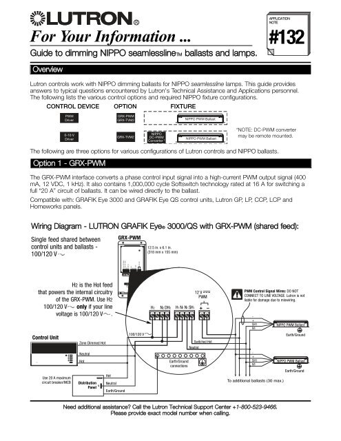
Lutron Sunnata Led Dimmer Switch With Wallplate For Incandescent Halogen Bulbs 150w Single Pole Only White Stwcl 153ph Wh The. Lutron Maestro 3 Way Dimmer Wiring Troubles. ムread Pdf Epub Mark 10 Dimming Ballast Wiring Diagram. Lutron Dv 603p Wh Diva 600w Incandescent Halogen 3 Way Dimmer In White. For Your Information.
Fluorescent Ballast Wiring Diagram - 8 foot fluorescent ballast wiring diagram, advance fluorescent ballast wiring diagram, compact fluorescent ballast wiring diagram, Every electric arrangement is composed of various diverse pieces. Each component ought to be placed and connected with different parts in particular manner. Otherwise, the structure won't function as it ought to be.
Jul 11, 2018 · dimmable ballast wiring diagram – What is a Wiring Diagram? A wiring diagram is an easy visual representation with the physical connections and physical layout of your electrical system or circuit. It shows the way the electrical wires are interconnected and may also show where fixtures and components could possibly be coupled to the system.

Mark 10 Dimming Ballast Wiring Diagram. for use with Advance Mark 10 or other Phase-Control ballasts. V and V. SCMark Wiring Diagrams and Ganging Information for HUNT Simplicity. ®. Philips Advance Mark 10® Powerline dimmable ballasts Wiring. Diagram. CFQ18W/G24q - 18W CFL Quad Tube Lamp (PL-C18W/4P, F18DBX/4P, CF18DD/E). Mark 10 Powerline ballasts for linear % - 5% full range continuous dimming (T5HO to 1%) For ballast dimensions and wiring diagrams see page 5.

Rapid start ballasts can only be wired in series according to the diagram on the ballast. Instant start ballasts can only be wired in parallel according to the diagram on the ballast. Changing the wiring on a fluorescent light fixture from rapid start to instant start, involves changing the wiring from series to parallel.
Lutron dimming ballast wiring diagram. Auma valve wiring diagram. Splan wiring diagram. Ttr 125 carburetor diagram. Cushman golfster 3 wheel golf cart 36 volt wiring diagram. 855t-b10dn4 ab steady incandescent wiring diagram. Wolff tanning bed wiring diagram. Mtb rapidstrike wiring diagram.

From the thousand images on the internet with regards to lutron dimming ballast wiring diagram, we picks the top choices with best image resolution just for you all, and this photographs is usually among graphics series in this finest graphics gallery regarding Lutron Dimming Ballast Wiring Diagram.I'm hoping you will want it. This specific graphic (Lutron 6B38 Wiring Diagram Lutron 3 Way ...

0-10 V Ballast/Driver Dimming With ON/OFF Control Wiring Diagram Using Relay Figure C1: Dimming With ON/OFF Control Via Relay Connect the control as shown in Figure C2. Do not install the Relay in the same wallbox as the low-voltage control. Refer to the wiring sheet included with the Relay for more information. 0-10 V Ballast/Driver White ...

T8 Fluorescent Ballast Wiring Diagram – Wiring Diagrams Thumbs – Ballast Wiring Diagram T8. Wiring Diagram consists of numerous detailed illustrations that show the relationship of varied products. It includes guidelines and diagrams for various kinds of wiring strategies along with other things like lights, home windows, and so on.
• Gray dimmer lead to (-) Gray connection on ballast. Proceed to Step 5. Wiring Diagram 1 Insulating Label Green Ground Black White Red Hot (Black) Neutral (white) Line 120/277VAC 60Hz Dimmer) Gray (-) Yellow To Lamps Red Blue 0-10 VDC Ballast Yellow/ Red 1 3 7 Matching Remote Additional Neutral Wire 2 Dimmer 2 3 4 Red Violet White Yellow/Red ...
Ballast bypass Led Wiring Diagram T8 T10 T12 Led Tube Lights 4ft 28w 6000k Cool White G13 Base Dual Ended Powered Frosted Cover 48 Fluorescent Light Replacement 25 Pack. Ballast bypass Led Wiring Diagram 4 Lamp Led Wiring Diagram Wiring Diagram All. Ballast bypass Led Wiring Diagram Schematic Of the Central Dimming System for Magnetic Ballast.
Description: Lutron 6B38 Wiring Diagram Lutron 3 Way Dimmer Troubleshooting for Lutron Dimming Ballast Wiring Diagram, image size 980 X 412 px, and to view image details please click the image.. Here is a picture gallery about lutron dimming ballast wiring diagram complete with the description of the image, please find the image you need.
THE EMERGENCY BALLAST WIRING GUIDE This Document has been customized to contain a wide library of individual dia-grams for various installation applications. If a diagram cannot be found within this selection, consult Customer Service. The diagrams are categorized primarily according to the number of lamps in the
Jan 28, 2018 · Or you are a student, or perhaps even you who just want to know concerning Lutron Dimming Ballast Wiring Diagram. Dimmable Ballast Wiring Diagram, size: 800 x 600 px, source: i0.wp.com. Whatever you are, we aim to bring the material that matches what you are trying to find. You might come from a search engine, after that discover this internet site.

A wiring diagram is a streamlined traditional photographic representation of an electric circuit. Make sure all connections are in accordance with the national electrical code and any local regulations. Select the appropriate wiring diagram on back to connect the emergency ballast to the ac ballast and lamp s.
4 T8 ballasts 7 T5 ballasts 8 CFL ballasts 9 Magnetic T12 conversion to electronic 9 Circline and signage ballasts 10 T12 ballasts 11 Controllable ballasts ... specifications, wiring diagrams, and more • Dynamic cross-reference tool — find equivalent Philips


0 Response to "39 dimming ballast wiring diagram"
Post a Comment