42 shear force and bending moment diagram problems and solutions pdf
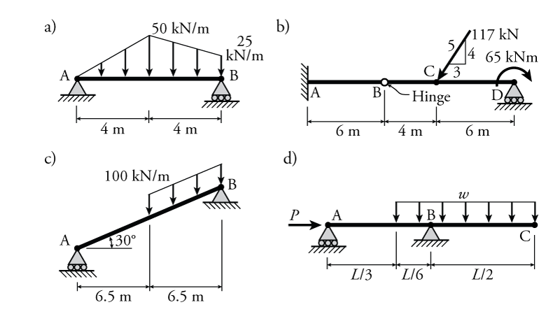
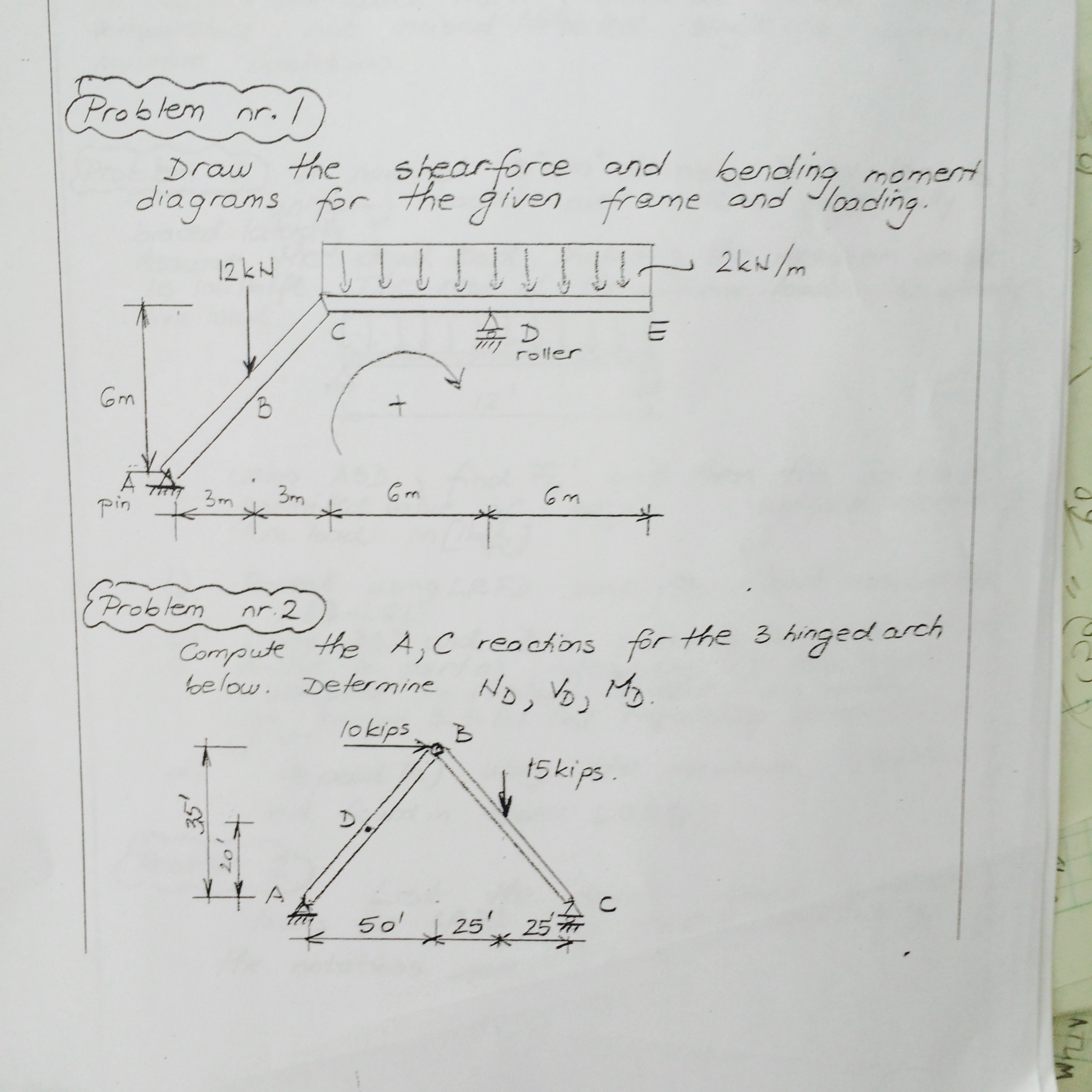
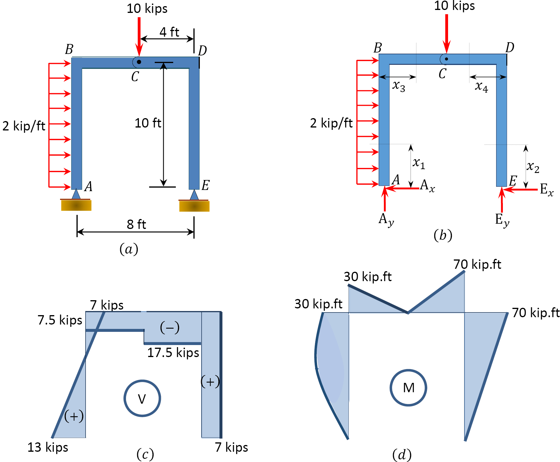
Calculate the support reactions and draw the Bending Moment diagram, Shear Force Diagram, Axial Force Diagram. Problem 3 3. Jan 06, 2021 · Shear and Bending Moment diagrams are drawn as shown below. Sep 18, 2020 · Ering mechanics statics pages 351 400 flip fliphtml5 consider the overhang beam shown in figure below draw shear and bending ... Concepts of Traction and Stress In general, Traction is the distributed force per unit area acting at a point on any (external) surface of a body or a part of a body. Traction is a vector represented with a 3x1 matrix in 3D. Stress is a physical quantity that completely characterizes the distributed internal forces per unit area that develop at a point within a body or a part of a body, at any ...
Problem 5: Bending Moment and Shear force; Problem 6: Bending Moment Diagram; Problem 7: Bending Moment and Shear force Problem 8: Bending Moment and Shear force; Problem 9: Bending Moment and Shear force; Problem 10: Bending Moment and Shear force; Problem 11: Beams of Composite Cross Section
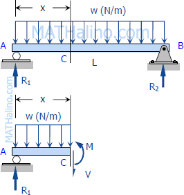
Shear force and bending moment diagram problems and solutions pdf
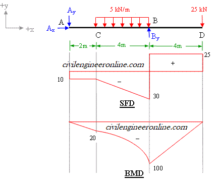
Shear as a measure of Following the second chemotherapy cycle, the patient was treated with Proton Beam Radiation. 78: For beam AB, (a) Draw the shear and bending-moment diagrams, (b) Determine the location and magnitude of the maximum absolute value of the bending moment. Draw the shear diagram for the beam set m0 500 nm l 8 m. degree in ... Mechanics of materials problems and solutions pdf. Mechanics of materials problems and solutions pdf [email protected] Mechanics of materials problems and solutions pdf ... Shear force and bending moment diagram problems and solutions pdf Shear Force Diagram is the Graphical representation of the variation of Shear Force Over the cross-section along the length of the beam. With the Shear Force Diagram’s help, we can identify Critical sections Subjected to Shear and design amendments to be made to avoid failure.
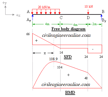
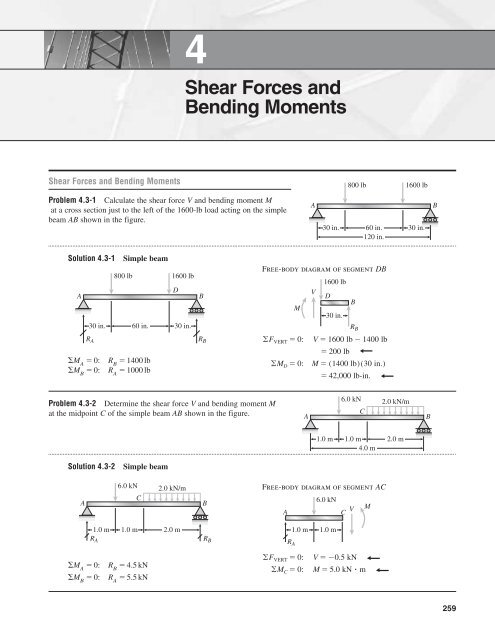
Shear force and bending moment diagram problems and solutions pdf. PDF_C8_b (Shear Forces and Bending Moments in Beams) Q6: A simply supported beam with a triangularly distributed downward load is shown in Fig. Calculate reaction; draw shear force diagram; find location of V=0; calculate maximum moment, and draw the moment diagram. 6k/ft 9 ft RA = (27k)(9-6)/9= 9k A B F = (0.5x6x9) = 27k x = (2/3)(9) = 6 ft Mechanics of materials problems and solutions pdf Mar 05, 2021 · Shearing force and bending moment diagram. The determined shearing force and moment diagram at the end points of each region are plotted in Figure 4.7c and Figure 4.7d. For accurate plotting of the bending moment curve, it is sometimes necessary to determine some values of the bending moment at intermediate points by inserting some distances ... Calculate the shear force and bending moment for the beam subjected to the loads as shown in the figure, then draw the shear force diagram (SFD) and bending moment diagram (BMD). 2 kN/m 3 m A B EXAMPLE 7
= 6internal bending moment = name for a moment vector n = number of connectors across a joint n.a. = shorthand for neutral axis (N.A.) O = name for reference origin p = pitch of connector spacing P = name for a force vector q = shear per length (shear flow) Q = first moment area about a neutral axis Q connected = first moment area about a neutral structural analysis problems and solutions ... Full PDF Package Download Full PDF Package. This Paper. A short summary of this paper. 14 Full PDFs related to this paper. Read Paper. Download Download PDF. Download Full PDF Package. Translate PDF. Related Papers. MEKANIKA TEKNIK 0I. … Quasi-static bending of beams. A beam deforms and stresses develop inside it when a transverse load is applied on it. In the quasi-static case, the amount of bending deflection and the stresses that develop are assumed not to change over time. In a horizontal beam supported at the ends and loaded downwards in the middle, the material at the over-side of the beam is compressed while the ... Jasbir S. Arora, in Introduction to Optimum Design (Third Edition), 2012 Step 1: Project/Problem Description. A beam of rectangular cross-section is subjected to a bending moment M (N·m) and a maximum shear force V (N). The bending stress in the beam is calculated as σ=6M/bd 2 (Pa), and average shear stress is calculated as τ=3V/2bd (Pa), where b is the width and d is the depth of the …
Statics of Bending: Shear and Bending Moment Diagrams David Roylance Department of Materials Science and Engineering Massachusetts Institute of Technology Axial Force, Shear Force and Bending Moment Diagrams for Plane Frames Previous definitions developed for shear forces and bending moments are valid for both beam and frame structures. However, application of these definitions, developed for a horizontal beam, to a frame structure will require some adjustments. 4.4 Area Method for Drawing Shear- Moment Diagrams Useful relationships between the loading, shear force, and bending moment can be derived from the equilibrium equations. These relationships enable us to plot the shear force diagram directly from the load diagram, and then construct the bending moment diagram from the shear force diagram. 4.3 Shear Forces and Bending Moments Consider a cantilever beam with a concentrated load P applied at the end A, at the cross section mn, the shear force and bending moment are found Fy = 0 V = P M = 0 M = P x sign conventions (deformation sign conventions) the shear force tends to rotate the material clockwise is defined as positive
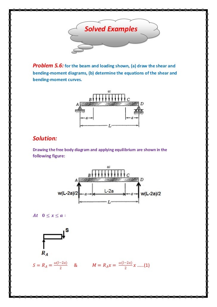
Problem 9: Bending Moment and Shear force A constant load of ω0 per unit length is applied on a simply supported beam as shown below. Draw the shear force and bending moment diagram by a. Method of sections b. Integration method Solution: Formulas used: dv dm qV dx dx = = . We first find the support reactions which are necessary for both the ...
Recall the formula used to calculate shear stresses due to bending, τ = VQ/It. We have just read the internal shear force, V, off of the shear diagram. We also already calculated the moment of inertia for this particular section. The remaining problem is that of calculating Q and t. Calculating Q(y 0) Hide Text 6
Shear force and bending moment diagram problems and solutions pdf Shear Force Diagram is the Graphical representation of the variation of Shear Force Over the cross-section along the length of the beam. With the Shear Force Diagram’s help, we can identify Critical sections Subjected to Shear and design amendments to be made to avoid failure.
Mechanics of materials problems and solutions pdf. Mechanics of materials problems and solutions pdf [email protected] Mechanics of materials problems and solutions pdf ...
Shear as a measure of Following the second chemotherapy cycle, the patient was treated with Proton Beam Radiation. 78: For beam AB, (a) Draw the shear and bending-moment diagrams, (b) Determine the location and magnitude of the maximum absolute value of the bending moment. Draw the shear diagram for the beam set m0 500 nm l 8 m. degree in ...

Pdf Chapter 5 Bending Moments And Shear Force Diagrams For Beams 5 0 Shear Force And Bending Moments Diagrams For Beams Petrus Guntur Supradana Academia Edu
Bending Moment And Shear Force In Statically Determinate Beams Solid Mechanics Structural Engineering Civil Gate Syllabus Paper Solution Question Answer
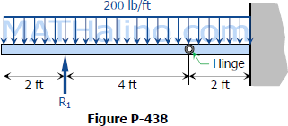
Solution To Problem 438 Relationship Between Load Shear And Moment Strength Of Materials Review At Mathalino

Learn Shear Force Bending Moment Online Problem On Sfd Bmd Bending Moment Shear Force In This Moment

Assignment 3 Pdf Assignment 3 1 Write The Equations For The Shear And Bending Moment For The Beam And Loading Shown 2 Draw The Shear And Bending Course Hero









0 Response to "42 shear force and bending moment diagram problems and solutions pdf"
Post a Comment