42 draw a ray diagram of the lens system in part d
1 Answer. animal tissue. question related to animal tissue. short questions of animal tissue. unstriated muscles. unstriated muscles in human body. On Friday, November 12 from 5:00 PM to 9:00 PM EST, the Quick Search and QPLDocs web sites will be unavailable due to system maintenance. The ASSIST Service Desk will not publish new documents in ASSIST until the system is fully operational on Monday, November 15. We apologize for the inconvenience that this may cause.
Nikon has officially released the Nikkor Z 28mm F2.8 - the non 'SE' version of a lens that we've been fans of for a while. Literally the only differences between this version and the previously released 'SE' are cosmetic. The new lens is housed in a more subdued, modern-styled matte black plastic barrel, in contrast to the retro-styled 'SE'.

Draw a ray diagram of the lens system in part d
It';d be really awesome if microprocessors, even at a low-end process node like 130 nm, could be made with room-sized machines or smaller. There's a lot of space for companies wanted to manufacture their own MCUs, for instance, without relying on massive supply chains. DMAIC is a data-driven problem-solving technique designed to identify and address inefficiencies in a process, which improves its outcomes and makes these improvements more predictable. The acronym stands for the five phases — Define, Measure, Analyze, Improve, and Control, and it is pronounced "duh-may-ik.". Ray-Ban's first-gen smart glasses bring a lot to the table, including a chance to star in a real-life dystopian sci-fi flick, controversially directed by Facebook.
Draw a ray diagram of the lens system in part d. The Physics Classroom serves students, teachers and classrooms by providing classroom-ready resources that utilize an easy-to-understand language that makes learning interactive and multi-dimensional. Written by teachers for teachers and students, The Physics Classroom is always thinking of new ways to expand and improve their reach into the lives of students, teachers and classrooms. Spec Sheet Lookup In a hands-on way, students explore light's properties of absorption, reflection, transmission and refraction through various experimental stations within the classroom. To understand absorption, reflection and transmission, they shine flashlights on a number of provided objects. To understand refraction, students create indoor rainbows. An understanding of the fundamental properties of light ... Parts of a Camera 1. Aperture. Aperture is the opening in front of the camera. It will be present in the lens part. For, an interchangeable lens camera, you will have the option to change the lens. So, you will have more options with the Aperture. But, for a standard point and shoot or bridge camera, the lens is a fixed one. So, the options are ...
The lens will be a part of Panasonic's F1.8 Lumix S prime lens lineup and will fill the gap between the current 14mm and 20mm prime lens options in the L-mount lens lineup. Nov 10, 2021 49 lens news Yongnuo has a new $310 50mm F1.8 AF full-frame lens for Sony E mount cameras on the way Which Of The Following Can Make A Parallel Beam Light From Point Source Is Incident On It. As Shown A Narrow Beam Of Light Is Incident Onto Semi Circular Gl Cylinder Radius R Can Exit The When At Centre. Draw A Diagram To Show How Converging Lens Focuses Parallel Ray Of Light Studyrankers. Applying the Three Rules of Refraction. In this section of Lesson 5, we will investigate the method for drawing ray diagrams for objects placed at various ... 10. Draw a ray diagram for Method I. · Part 2: Diverging Lens to determine the focal length of a diverging lens, the · Name: Worksheet - Exp 22: Thin Lenses ...
a, Free energy diagram of Ti-OH − adsorption and Ti-OH * creation in the context of the full reaction scheme. Photo-excitation (yellow arrow) separates the diagram into the dark, equilibrated ... The curvature of a spoon inward toward its middle is a common example of a concave mirror. Learn more about the definitions of a concave mirror, the law of reflection, and the mirror equation, as ... b) Draw a ray diagram of the lens system in part D. C. DETERMINING YOUR BLIND SPOT The cells on your retina are wired in such a. D. MEASURING FOCAL LENGTHS ... Draw the ray diagram and then answer the questions given concerning the system. ... Part D What is the angular magnification of the system if the eye is ...
Physics Tutorial Refraction And The Ray Model Of Light
To use the anagram solver, just pop your letters into the search field and the anagram generator will do the rest. Enter up to 20 letters into the anagram search box. Don't worry about spaces if you're trying to solve an anagram with multiple words. When you're done entering your letters, hit the search button on the right.

Ray Diagrams For Lenses Light Science Physics Diagram
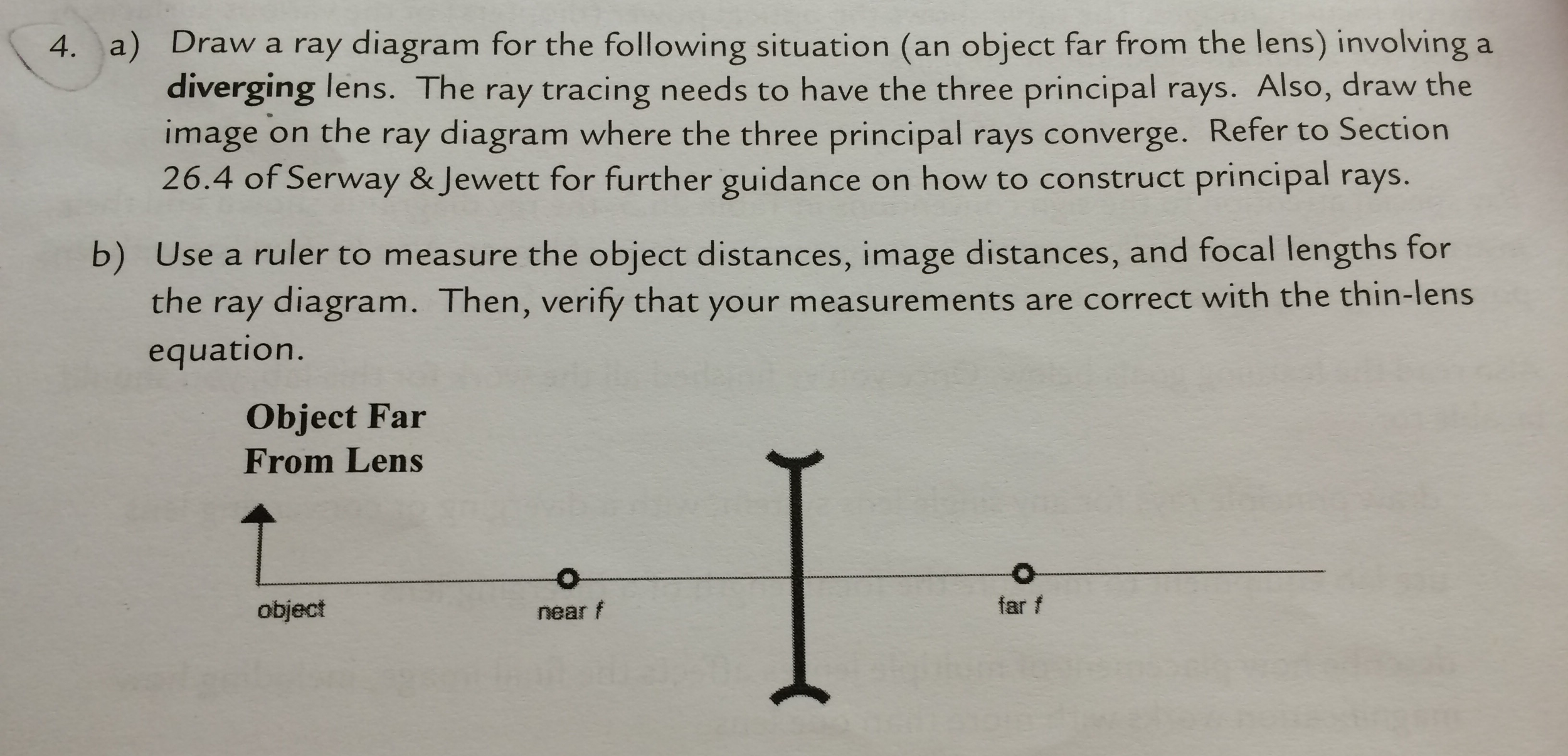
A) Draw a ray diagram for the following situation (an object far from the lens) involving a diverging lens. The ray tacing needs to have the three principal ...Missing: d | Must include: d
Amherst Edu
The angle of incidence can refer to a number of entities: in optics, the angle of incidence is the angle that the incident ray makes with the line drawn perpendicular from the point of contact on a surface. In aerodynamics, the angle of incidence refers to the angle between the chord of the wing of an aircraft and the longitudinal axis of the fuselage

A Draw A Ray Diagram For The Following Si Clutch Prep
Total internal reflection (TIR) is the optical phenomenon in which waves arriving at the interface (boundary) from one medium to another (e.g., from water to air) are not refracted into the second ("external") medium, but completely reflected back into the first ("internal") medium. It occurs when the second medium has a higher wave speed (lower refractive index) than the first, and the waves ...

New Page 1
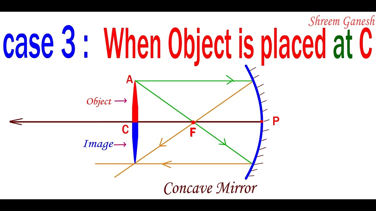
d. When the object is placed between principal focus and center of the curvature e. When the object is placed at the principal focus f. When the object is placed between the pole and principal focus. Concave Mirror Diagram. The ray diagram of concave mirrors based on the object placement stated above are given below: Source: NCERT Book

Draw A Ray Diagram In Each Of The Following Cases To Show The Formation Of Image When The Object Is Placed I Between Optical Centre And Principal Focus Of A Convex Lens Ii
The front and back parts of the eye must work together to allow mammals to see and make sense of the outside world. The Parts of the Eye. Iris: the colored part of the eye. Pupil: the dark circle ...

Different Lens Ray Diagram Questions Evan S Space
This article lists a series of labeled imaging anatomy cases by system and modality. On this page: Article: Brain. Head and neck. Spine. Chest.

Using Ray Diagrams To Better Understand Everyday Reality Demo Keerthi Vasan Gc
To provide a complete Learning Management System around the Virtual Labs where the students/ teachers can avail the various tools for learning, including additional web-resources, video-lectures, animated demonstrations and self-evaluation. Good lab facilities and updated lab experiments are critical for any engineering college.
Solved A Draw A Ray Diagram For The Following Situation An Chegg Com
60 cm om 1 d - Part A Find the image by drawing a ray diagram with all three principal rays on your tracing. 6.0 cm 6.0 cm 6.0 cm 1 d f 6.0 cm If d Submit ...

16 3 Lenses Texas Gateway
Finding the image distance for varying object distances in case of a convex lens and drawing corresponding ray diagrams to show the nature of the image formed. Identification of the different parts of an embryo of a dicot seed (Pea, gram or red kidney bean). Internal Assessment. Management of natural resources: science class 10 deleted syllabus
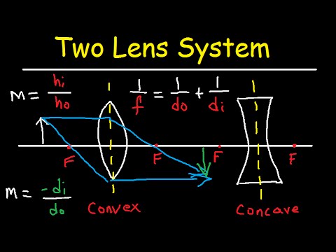
Multiple Two Lens System With Diverging And Converging Lens Youtube
A Wipeout is an image type object. Most commonly it is used to "mask" part of a drawing for clarity. For example, you may want to add text to a complicated part of a drawing. A Wipeout could be used to mask an area behind some text so that the text can easily be read, as in the example shown on the right.

16 3 Lenses Texas Gateway
Here's what's new in Whoop 4.0 versus Whoop 3.0: - New sensor: This now has 5 LEDs (3xGreen, 1xRed, 1xInfared) compared to the previous 2xGreen. It now has 4 photodiodes, versus the 1 previously. - Added Skin Temperature: We've seen this on a few wearables over the years, and is often used with sleep data.

Converging Diverging Lenses Ray Diagrams Directions Use At Least Two 2 Rays With Different Colors Homeworklib
A headlamp is a lamp attached to the front of a vehicle to illuminate the road ahead. Headlamps are also often called headlights, but in the most precise usage, headlamp is the term for the device itself and headlight is the term for the beam of light produced and distributed by the device.. Headlamp performance has steadily improved throughout the automobile age, spurred by the great ...

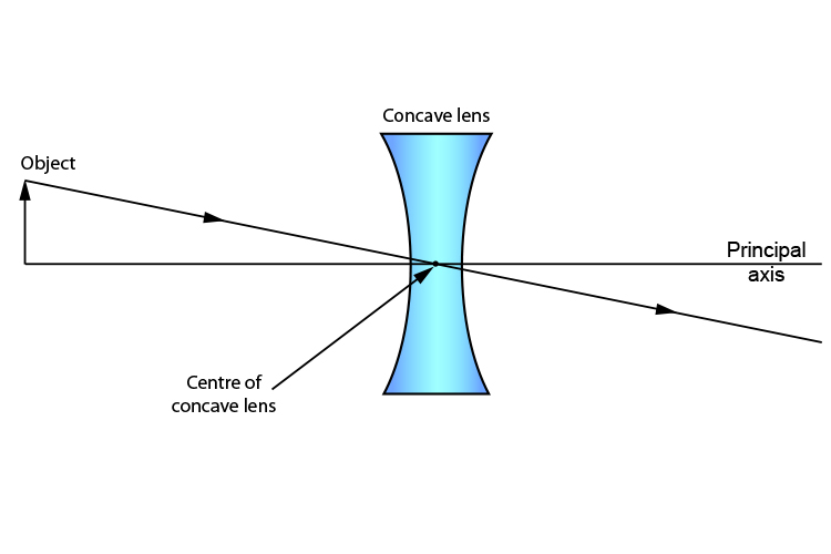
Draw Diagrams Showing Image Formation By The Following Indicating The Optical Centre Principal Axis Principal Focus And Focal Length I A Concave Lens And Ii A Convex Lens
The Endurance 10 watt "Invincible" diode laser module with 445 nm wavelength. Converts any 3D printer or CNC machine into a powerful laser cutting and engraving tool. Cuts wood, plywood, acrylic. Engraves on steel, copper, and anodized aluminum.
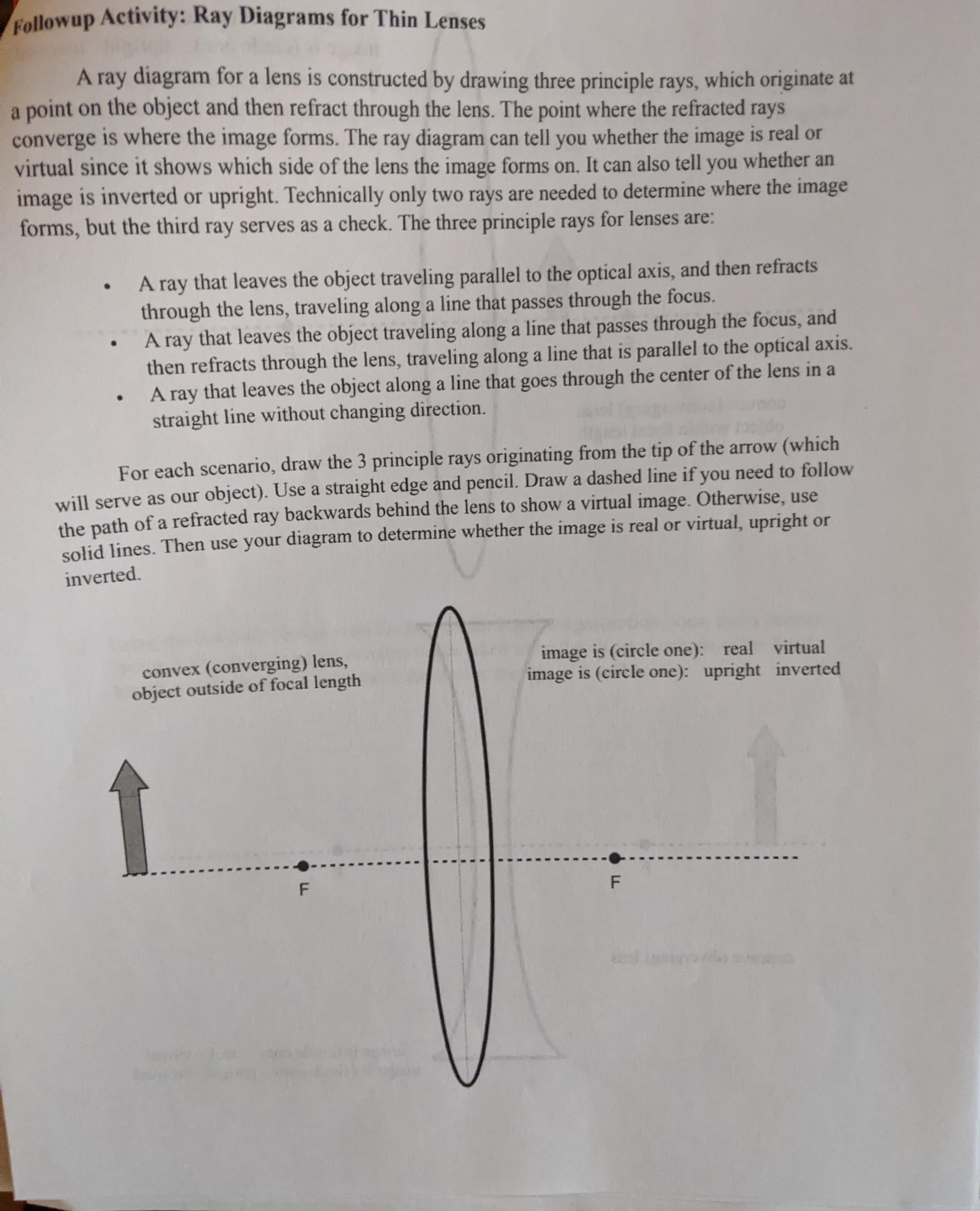
Solved Followup Activity Ray Diagrams For Thin Lenses A Ray Chegg Com
An electromagnetic coil (the first lens) concentrates the electrons into a more powerful beam. Another electromagnetic coil (the second lens) focuses the beam onto a certain part of the specimen. The specimen sits on a copper grid in the middle of the main microscope tube. The beam passes through the specimen and "picks up" an image of it.
1
Concave Mirror Ray Diagram. With the help of ray diagrams, we can understand how images are formed in concave mirrors. We should consider at least 2 incident rays coming from an object to understand the image formation in Concave Mirrors. The intersection of 2 rays after reflection provides the image position of an object.

Draw A Ray Diagram Representing Your Experiment From Part C Wiring Site Resource
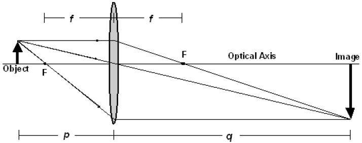
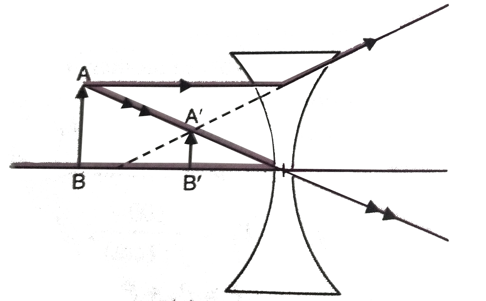
First, we draw a ray parallel to principal axis. So, it passes through focus after refraction. We draw another ray which passes through Optical Center. So, the ray will go through without any deviation. Where both rays meet is point A'. And the image formed is A'B'. This image is formed between F 2 and 2F 2. We can say that.

Draw A Ray Diagram Representing Your Experiment From Part C Wiring Site Resource
Ray-Ban's first-gen smart glasses bring a lot to the table, including a chance to star in a real-life dystopian sci-fi flick, controversially directed by Facebook.
Thin Lenses And Lens Systems
DMAIC is a data-driven problem-solving technique designed to identify and address inefficiencies in a process, which improves its outcomes and makes these improvements more predictable. The acronym stands for the five phases — Define, Measure, Analyze, Improve, and Control, and it is pronounced "duh-may-ik.".

Ray Diagrams Lenses Physics Lab Video Lesson Transcript Study Com
It';d be really awesome if microprocessors, even at a low-end process node like 130 nm, could be made with room-sized machines or smaller. There's a lot of space for companies wanted to manufacture their own MCUs, for instance, without relying on massive supply chains.
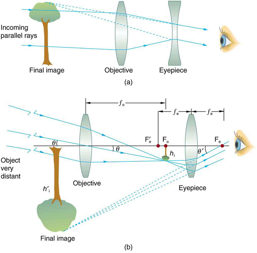
Telescopes Physics

18 Draw A Ray Diagram For The Following Positions Of The Object Placed In Front Of A Convex Lens 5 Brainly In

Drawing Ray Diagrams For A Converging Lens The Fizzics Organization
Lenses Boundless Physics

Draw Diagrams Showing Image Formation By The Following Indicating The Optical Centre Principal Axis Principal Focus And Focal Length I A Concave Lens And Ii A Convex Lens
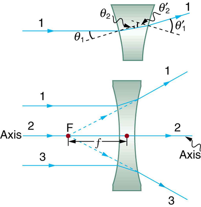
Method For Drawing Ray Diagrams Concave Lens
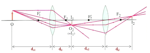
Two Lens System Image Distance And Magnification
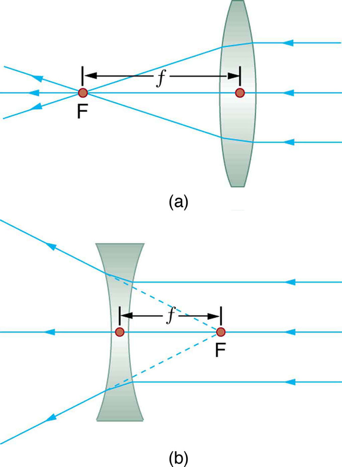
Lenses Boundless Physics
Stsauhg11physics Pbworks Com

Draw Ray Diagrams To Represent The Nature Position And Relative Size Of The Image Formed By A Convex Brainly In
Cyberphysics Rules For Drawing Ray Diagrams

Ray Diagrams 2 Of 4 Convex Lens Youtube
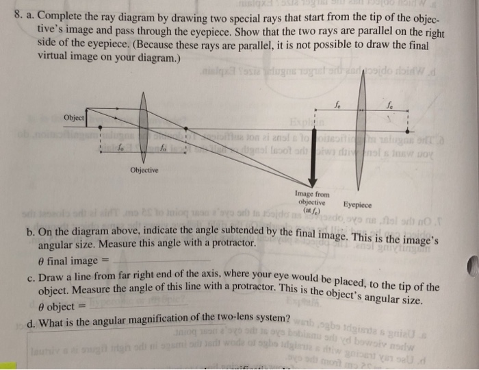
Solved 8 A Complete The Ray Diagram By Drawing Two Special Chegg Com
If The Image Formed By A Lens For All Positions Of An Object Placed In Front Of It Is Always Erect And Diminished What Is The Nature Of This Lens Draw

Mr Toogood Physics Lenses
Draw A Ray Diagram Representing Your Experiment From Part C Wiring Site Resource
Object At Infinity Concave Mirror
Solved Followup Activity Ray Diagrams For Thin Lenses A Ray Chegg Com

Draw A Ray Diagram To Show The Image Formation By A Combination Of Two Thin Convex Lenses To Contact Obtain The Expression For The Power Of This Combination In Terms Of The
Day 27 Drawing Ray Diagrams Lenses Mrcampbellsscienceclass
Ss Ray Diagrams For Converging Lens Mini Physics Learn Physics

Drawing Ray Diagrams For A Converging Lens The Fizzics Organization
0 Response to "42 draw a ray diagram of the lens system in part d"
Post a Comment