41 nitrous relay wiring diagram
When running a "dry" nitrous setup with the Holley Terminator X, additional fuel when on nitrous is injected through the existing fuel system. To meet the fuel needs of a 150-hp shot, we replaced the factory 19-lb/hr fuel injectors with these Holley 36-lb/hr injectors (p/n 522-368) and a Holley 190 lph in-tank pump (p/n 12-901). Configuring And Wiring Sniper Efi System For Nitrous Oxide. Update installed full nitrous set up stage 3 pcm wiring diagram install stangnet help for my kit gauge cold fusion leash single sportsman tps and tach signal purge read all instructions before beginning terminator x efi system to run window switch relay multistage nos mini controller ls1tech carburetor plate systems board how wire an ...
52 No Nc Switch Diagram. The NC contact of a limit switch, when used in a circuit breaks the circuit or current flow when its actuator is pressed. Similarly, the contacts of a relay remain closed unless its coil is excited. Remains closed until a certain condition is satisfied. The above image shows the NO and NC arrangement of a limit switch ...
Nitrous relay wiring diagram
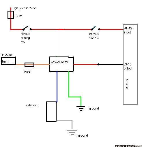
4,950 Posts. #6 · Dec 23, 2005. If you get no where with this PM me, I have a diagram get me your email and I will send it out or if you tell me every componet for the nitrous your running I can custom build a diagram for yor application. progressive, trans brake, retard module Etc. Originally Posted by Danny Cabral The Sniper EFI electric fan ground wires (pin C, light blue - Fan #1 & pin D, light green - Fan #2) trigger the relay coil − (terminal #85). Yes, terminal #85/Ground is the industry standard for good quality relays, with or without a diode.Sniper EFI instruction manual: LINK - page 17 & 50. Electric Fan #1/#2 relay terminals (ECU ground signal scenario): September 16, 2021 - Read Or Download Pin Automotive Relay Switch For FREE Wiring Diagram at CDLMANUAL.ARTSCONNECTION.IT
Nitrous relay wiring diagram. Relay Normally On Circuit With Positive Trigger Wiring Diagram ... Wiring Diagram For 5 Pin Relay For Drl With Turn Signal Wire NOS systems are calibrated for optimum performance with a bottle pressure of 900- 950 psi. The pressure will change with temperature. Heater kits are thermostatically controlled (except P/N 14169NOS, which is pressure controlled) to keep the bottle at correct pressure. Kits available for the most popular-sized bottles, with both 12-volt and 110-volt heaters offered. Built with only OEM connectors and TXL wire, we hand build each harness on an actual engine and test it on a dyno to assure proper fitment, function, and concept. The kits come complete with a weatherproof fuse and relay box that you can mount. Ls ecu and harness. A popular option for Sand Rails, buggies, and anything else you can set a 4cyl ... At NX and Snow Performance, we live and dream Nitrous Oxide and Water Methanol. Customer service is taken very seriously and we work constantly to develop and improve our product lines. Our company is comprised of experienced and passionate people who use our products every day.
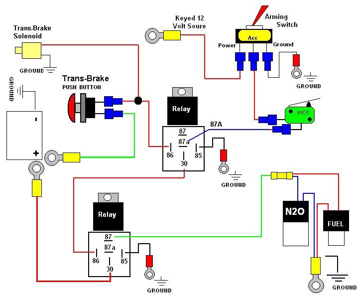
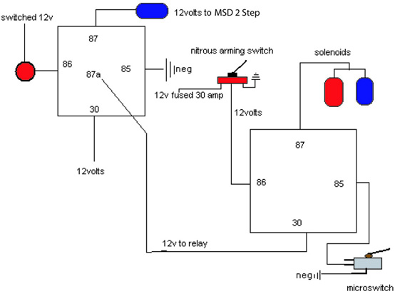
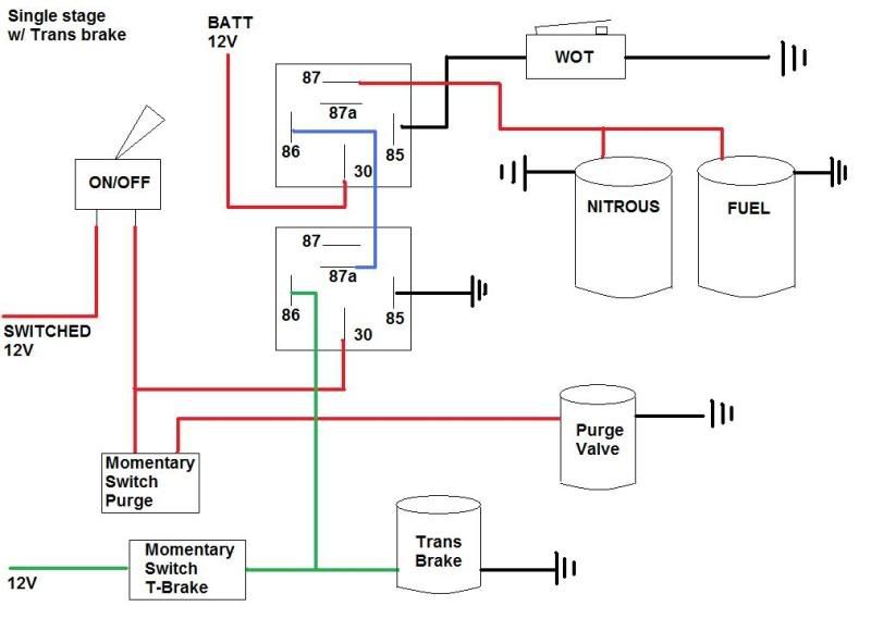
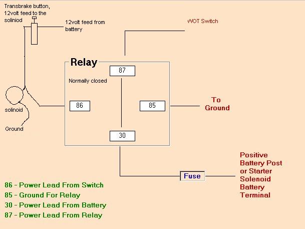
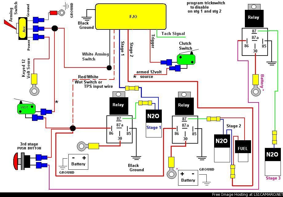
Nitrous Wiring Diagram With Transbrake. The stud labeled "2" is for the transbrake. It is activated by applying +12volts. If you have any questions, email daver@wiringall.com or call When wired in series with your nitrous system relay it will enable you plished by splicing into the trans brake ... Nitrous and Mallory 685 wiring diagram ... I don't think this was posted before, but it's a good diagram. ... is routed in series with the nitrous ... Nitrous Oxide - FPSS wiring without a relay - Tried searching, but I couldn't find a clear answer I'm doing a push button style setup (yes with all the safety devices!), but I'm a little puzzled on how to wire up a FPSS. I made a diagram showing my wiring from the WOT switch to the solenoid ... The proof of understanding is the ability to explain it. (H. Torruella) Ignorance is bliss, but stupidity is orgasmic. Fraud and falsehood only dread examination. Truth invites it. (Samuel Johnson) The chaotic resistance of the opponents leads to the conclusion that they are not prepared to meet the challenge.
nitrous outlet project: opener wiring diagram filename: opener wiring diagram.ai created date: 08/14/2020 pages: contact information: 2 of 2 rev #: 02 opener arm heater opener purge 87 87a 86 30 85 87 87a 86 30 85 opener relay 1 open close opener relay 2 opener 1 ground battery anel 3 2 2 1 ... Wiring Diagram. Class 8502 Type PE Contactor w/ Class 9065 Type TE Overload Relay.-20V 4age Silvertop Wiring Diagram - Click to download Official wiring diagram for a Silvertop sourced from Toyota and translated by an alien individual. -20V 4age wiring diagrams - Page 1, Page 2. These two pages are appear to be for the 20V Blacktop agent but ... DC Solid State Relay Wiring Diagram 1.1 DC to DC Solid State Relay. MGR-1DD series. The DC to DC solid state relay is a four-terminal electronic device that uses a DC signal to control the DC load. The 1 and 2 ports of DC-DC solid state switch are connected to the load and the DC power supply,. Variety of solid state relay wiring diagram. When wired in series with your nitrous system relay it will enable you plished by splicing into the trans brake solenoid wiring and using this power source to. Mar 29, Nitrous Oxide - wiring diagram of 2 step, NOS throttle switch and I need to 2 step and transbrake at rpm or so and have my NOS.
Stage 3 Pcm Nitrous Wiring Diagram Cobalt Ss Network
Nitrous Express Nx 16008 Maximizer 5 Progressive Controllers Summit Racing. Tested Nitrous Express Maximizer 4. Car Radio Wiring Diagrams Free 35 Images Delco Stereo Diagram Jvc Pioneer. Untitled nitrous express maximizer 5 relay panel read all instructions before beginning diagram wiring magnetic ...

Nos Nitrous Nx Zex Holley Bigshot Cheater 4an 3an 12 Line Hose Blue Or Red New Ebay
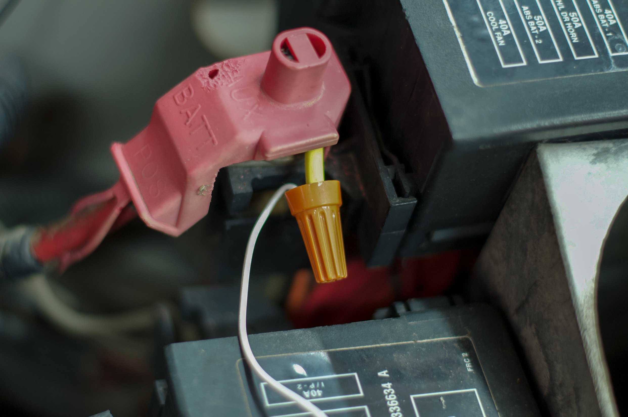
As long as the pink wire is switched with the ignition, all you need to run to the solid state relay is the small blue wire to one of the lower terminals (as long as the terminal block itself is grounded as well), and the large blue wire that feeds power to the pump on the corresponding output. 10-07-2021, 06:41 PM #4. 68_greenbird.

Time Delay Switch For Nitrous Oxide Works Like Digi Set But Nicer And Compact For Nitrous Oxide Systems Time Delay Switch For Nitrous Or Co2 Applications Like Digi Set But Nicer
Nitrous Oxide Info ... All Nitrous Kits ... Wet Kit Electrical Drawing Without Relay
2
Headlight Relay Kit A More Factory Looking Alternative Wiring Diagram ... 2003 Subaru Forester Left Headlight Wiring Diagram
Nitrous Wiring Diagram Help S2ki Honda S2000 Forums
Nos Relay Wiring Diagram from tse1.mm.bing.net Effectively read a cabling diagram, one offers to learn how the particular components in the system operate. For instance , in case a module will be powered up and it also sends out a signal of fifty percent the voltage and the technician would not know this, he would think he has a challenge, as ...
2
That being said, you can do up your own relay using the factory wiring as the trigger wire for like $15 in relay, wire, and terminals. 1991 Notch 347, 205 11R's, Box R Intake, Ported lower, fti cam, 80lb injectors, 90mm TB, LT's, A5 trans, 4.10, pimpxs, nitrous.
Nitrouscontrolwiring Ecmtuning Wiki
Nitrous Wiring Diagrams by John Heard Last Updated Jan 4 2015 Single Stage NOS System with Transbrake Interrupt Relay. Nitrous Wiring Diagram With Transbrake The stud labeled 2 is for the transbrake. Nitrous aperture 305 south 28TH artery waco tx 76634 2548484300. This dry nitrous system is advised for Fuel Injected Motorcycles Only!
2
JavaScript is disabled. In order to shop on this Web store, you must have JavaScript enabled · For instructions on how to enable JavaScript, please see the help section of your browser. Once JavaScript is enabled please refresh the current page

Digital Delay Nitorus Boards High Current 2 Stage Nitrous Relay Board
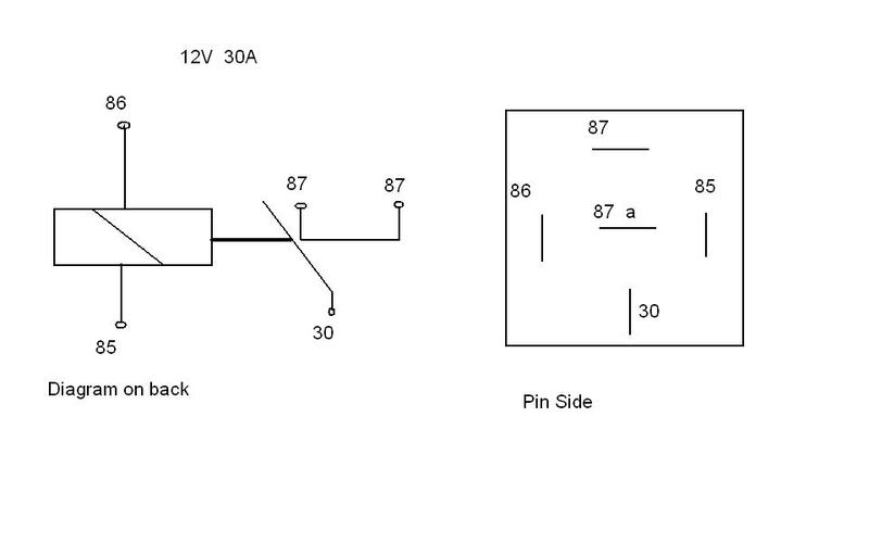
September 16, 2021 - Read Or Download 87a Relay For FREE Wiring Diagram at MANUALSLB.ARTSCONNECTION.IT

Nitrous Outlet Promax Relay Panel Pronitrous Com
Nitrous Relay Wiring Diagram Electrical Diagrams New Transbrake All With ... Nitrous Transbrake 2 Step Nitroustbrake Random Wiring Diagram With
Wet Kit Wiring Diagram Tccoa Forums
Haneline gauges wiring diagram. Innovate Motorsports Releases Gauges will require minor wiring revisions. Timing Relay Wiring Diagram Fresh Wiring Diagram Timer Relay Fresh. Nov 25, 2005 · Their Haneline elite is similar, but I'm not too sure 'bout the 'inverted swoosh' graphic on the gauge face. FN Thomson Reuters Web of Science™ VR 1.
2
41 Interrupter Relay Diagram. Written By Martin M Walker Wednesday, September 22, 2021 Add Comment. Edit. A latching relay is used to control the large flow of current with a smaller current. The coil of the latching relay consumes power only while the relay is switched ON. And its contact remains in position after the switch has been released.

Edelbrock Nitrous Wiring Diagrams Pdf
Forgot your Password · Contact Us - About Us - Archive - Advertising - Cookie Policy - Privacy Statement - Terms of Service - Do Not Sell My Personal Information

Problem With Relay And Solenoids For Nitrous Honda Civic Forum
Wire Ford Transit Connect Wiring Diagram Wiring Diagram Regular More ... Yamaha Golf Cart Wiring Diagram Further Nitrous Relay Wiring Diagram

Nitrous With Transbrake Wiring Diagram Auto Electrical Wiring Diagram
NOS explains how to properly wire a variety of NOS nitrous oxide systems, including dry, wet, plate and direct port fogger systems.
Need A Wiring Diagram Page 4 Yellow Bullet Forums
The diagram below shows how to wire a solid state relay. Please note that the diagram refers to DC/DC type solid state relay (SSR). a solid state relay is to construct a simple test circuit consisting of a DC power supply or battery (a 9Vdc battery will work fine in most cases) and a 60W or 100W light bulb. Fig. 1 below shows the basic wiring ...
2
The physical wiring diagram of the solid-state relay used for electromechanical equipment is as follows, but it is generally widely used in the chemical industry, coal mine, and other fields, and requires explosion-proof and corrosion resistance. Figure 5. SSR Wiring Diagram. Wiring the relay controller.
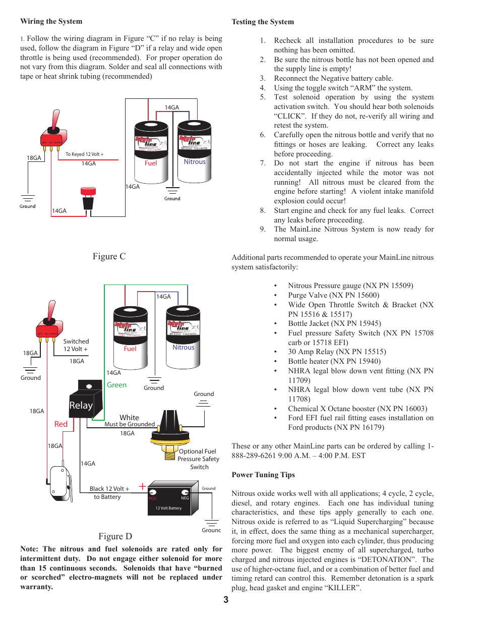
Relay Figure D Figure C 3 Nitrous Express Mainline Nitrous Systems User Manual Page 3 4
Nitrous Related Wiring Page 2 Ls1tech Camaro And Firebird Forum Discussion. Nitrous system wiring diagrams dragstuff nos and transbrake ls1tech trans brake express manualzz diagram tci 2 step holley performance products forums leash single stage relay board sniper efi double throw 60 amp pn ...
Nitrous Wiring Nitrous Hayabusa Owners Group
Nitrous Wiring Diagrams. The stud labeled 2 is for the transbrake. Aem Ems 4 96 Wiring Harness With Fuse Relay Panel 30 2905 96 . These Wiring Diagrams will help you wire up your Nitrous System or Nitrous Accessory. Nitrous relay wiring diagram. When wired in series with your nitrous system relay it will enable you plished by splicing into the trans brake solenoid wiring and using this power ...
Line Lock With 2 Step But Separate Nitrous
Relay kit 30amp minimum holley pn or equivalent the best location for mounting. This will ensure that the pump will not. 2 to wire the fuel pump with an oil pressure safety switch. In this episode we will walk through how to install some non essential but totally necessary accessories on the.
Nitrous Wiring Diagram Camaro Forums Chevy Camaro Enthusiast Forum
Download Images Library Photos and Pictures. Diagram Holley Fuel Pump Wiring Diagram Full Version Hd Quality Wiring Diagram Efiperfwiring Apposrl It Wiring Diagram Msd Solid State Relay 1985 Ford Mustang Holley My Garage Wiring Fuel Pump Circuit With Oil Pressure Switch And Relay Questions The 1947 Present Chevrolet Gmc Truck Message Board Network 12v Relay Wiring Diagram Fuel Pump Aamidis ...
Nitrous Wiring Nitrous Hayabusa Owners Group
Nos 15620nos solid state relay ships warning connecting battery voltage to wiring diagram msd stand alone how wire the mgr camaro5 chevy camaro forum zl1 experts please come nitrous system diagrams dragstuff Nos 15620nos Solid State Relay Ships Free At Efisystempro Com Warning Connecting Battery Voltage To The Blue Wire Will Damage Relay Verify Connections Before Applying… Read More »
Wiring Window Switch To Nitrous Kit Ls1tech Camaro And Firebird Forum Discussion
Nitrous Wiring Diagrams ... Single Stage NOS System with Transbrake Interrupt Relay . ... Single Stage NOS System with Transbrake Interrupt Relay ...

Obd1 Honda Ecu Nitrous Setup Guide For Hondata S300 And Neptune Xenocron Tuning Solutions
Nitrous Relay Wiring Diagram Inspirationa Colorful Solid State Relay ... Wiring Diagram Solid State Relay New Nos Relay Wiring Diagram
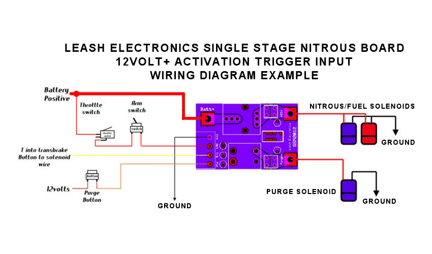
Leash Single Stage Nitrous Relay Board With Transbrake Interrupt Ssnb
*Wire the signal output wire from a 0-5v sensor to the appropriate pin using the Holley wiring diagram. All 0-5v sensors require a 5 volt reference voltage and a sensor ground. Each Holley EFI connector that has 0-5v inputs has it's own 5 volt reference voltage output and sensor ground. These need to be properly wired to each 0-5v sensor used.
1
Read Or Download Nitrous Relay For FREE Wiring Diagram at STEREODIAGRAM.VINCICONMAREBLU.IT
Nitrous Oxide System Installation Help Cold Fusion Nitrous
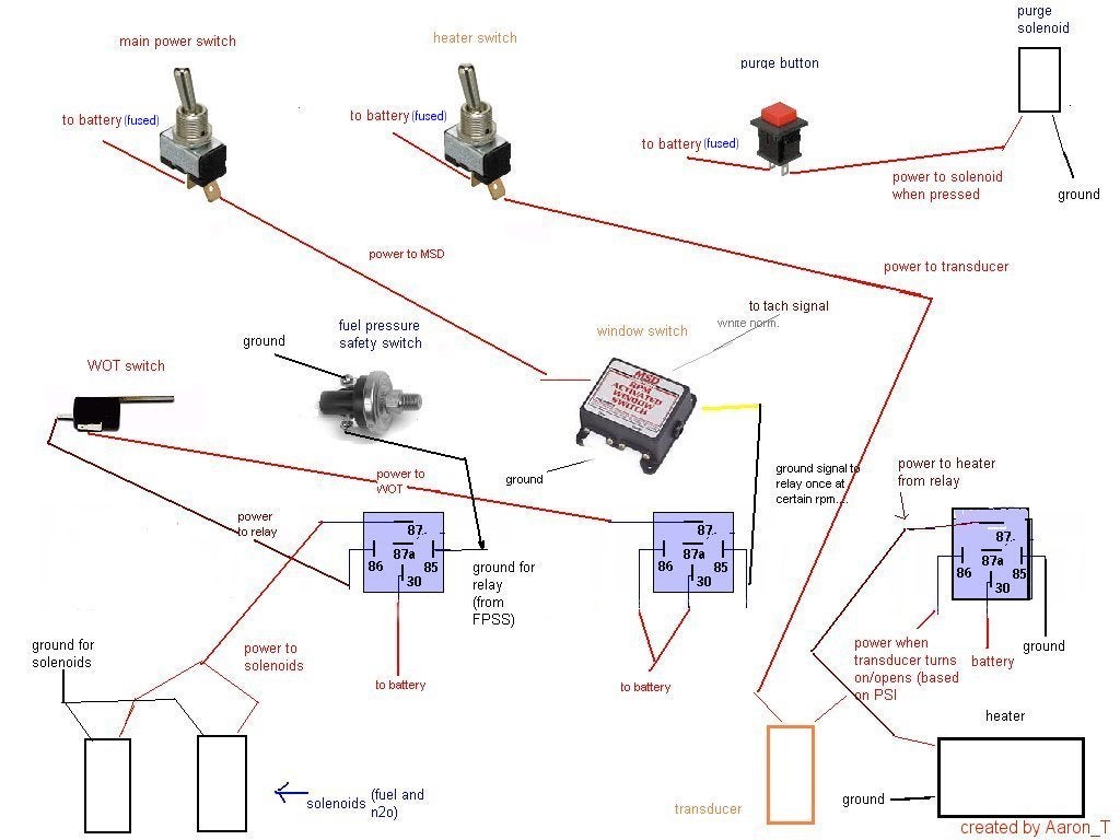
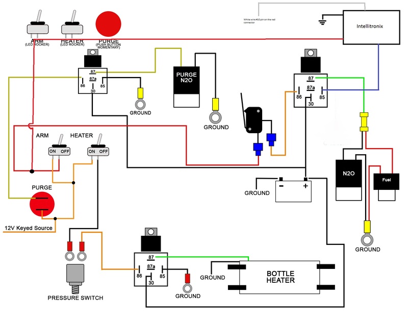
9. Connect the Red relay wire to one side of your heater transducer. The other terminal will connect to the toggle switch’s ACC terminal using the 18gauge blue wire supplied with your heater. The toggle switch must be connected to a 12-volt source controlled by the ignition switch.
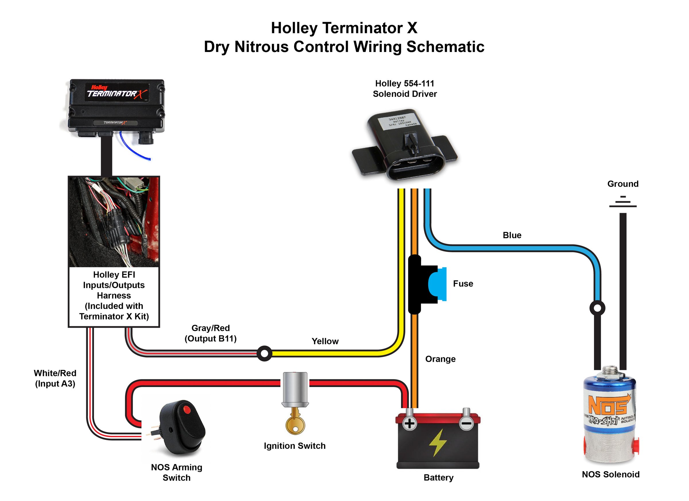
How To Set Up A Terminator X Efi System To Run Nitrous On A Foxbody Mustang Holley Motor Life
February 1, 2002 - Due to the EU's Global Data Protection Regulation, our website is currently unavailable to visitors from most European countries. We apologize for this inconvenience and encourage you to visit www.motortrend.com for the latest on new cars, car reviews & news, concept cars and auto show coverage, ...

Lt1 Nitrous Activation Problem Ls1tech Camaro And Firebird Forum Discussion
Name: solid state relay wiring diagram – Nitrous Relay Wiring Diagram Inspirationa Colorful Solid State Relay Wiring Diagram Best For

Nos Relay Wiring Diagram Diagram Base Website Wiring Diagram Electrical Circuit Diagram
Current Orders Lead Time: Bigger Relay Modules around 2-3 weeks. Little small board(1 and 2 relay boards) orders ship sooner. A week or two. Nitrous and Boost controllers are around a 1-2 week lead time.
Wiring Diagram For Fogger Yellow Bullet Forums
Basic Relay Diagram Iow What Goes Where Wiring Diagram ... Diagram Basic Relay Diagram Iow What Goes Where Wiring Diagram
Nitrous Transbrake And 2 Step Question Third Generation F Body Message Boards
1976 rupp nitro magnum snowmobile parts manual pdf by heys issuu dodge wiring diagrams car electrical diagram 2001 durango full version hd quality dpdt alel pastafrescacarmelaocone it alarm utos fritto hondad book honda f4i flashback the 1975 f a snowgoer jeep basic cj power antenna mitsubishi montero sport xls 1999 system diagramas de cableado para automóviles bartolini pickups… Read More »

Nos 15620nos Nos Solid State Relay
This manual contains information and diagrams related to wiring most Holley EFI products including ECU's, ignition systems, nitrous systems, water/methanol injection systems, sensors, and more. 3 1.1 Important Wiring "Do's and Don'ts.

Nitrous Kit Wiring Ford Mustang Forums
An electric fuel pump. This manual contains information and diagrams related to wiring most holley efi products including ecus ignition systems nitrous systems watermethanol injection systems sensors and more. It shows the elements of the circuit as streamlined shapes and the power as well as signal links in between the gadgets.

Nitrous Outlet Winmax Relay Panel Pronitrous Com
These Wiring Diagrams will help you wire up your Nitrous System or Nitrous Accessory. Includes Nitrous Purge, Nitrous Bottle Heater, and Dedicated Fuel System.

Wiring Diagram Motorcycle Horn Gambarin Us Post Date 04 Dec 2018 78 So Sistemas Automotrices Mecanico De Autos Circuitos Electronicos Para Armar
2 position toggle switch wiring diagram; 2 stage nitrous wiring diagram; 20 amp generator plug wiring diagram; 20 amp twist lock plug wiring diagram; 20 hp kohler command wiring diagram; 200 amp main panel wiring diagram; 2000; 2000 cbr 600 f4 wiring diagram; 2000 chevy cavalier 2.2 starter wiring diagram; 2000 chevy cavalier starter wiring diagram
Top 5 Nitrous System Installation Mistakes With Nitrous Outlet
I preface this post by saying I know very little about 12 volt electronics, but I'm working hard to learn. I've had a nitrous oxide system installed by a performance shop that includes an electric bottle warmer that is controlled by a pressure switch and relay. What I'd like to do is wire in an indicator light to let me know when the relay is either open or closed. It doesn't matter to me which way the light indicates. The solution that seems the simplest is to run terminal 85 to a bulb, ...
Nitrous Related Wiring Page 3 Ls1tech Camaro And Firebird Forum Discussion
September 16, 2021 - Read Or Download Pin Automotive Relay Switch For FREE Wiring Diagram at CDLMANUAL.ARTSCONNECTION.IT

Pin On Projects To Try
Originally Posted by Danny Cabral The Sniper EFI electric fan ground wires (pin C, light blue - Fan #1 & pin D, light green - Fan #2) trigger the relay coil − (terminal #85). Yes, terminal #85/Ground is the industry standard for good quality relays, with or without a diode.Sniper EFI instruction manual: LINK - page 17 & 50. Electric Fan #1/#2 relay terminals (ECU ground signal scenario):

Lqqk Sale Nos Nx Zex Edelbrock Holley Nitrous System Power Relay W Harness New 12 98 Picclick
4,950 Posts. #6 · Dec 23, 2005. If you get no where with this PM me, I have a diagram get me your email and I will send it out or if you tell me every componet for the nitrous your running I can custom build a diagram for yor application. progressive, trans brake, retard module Etc.
Zex Nitrous Question Svtperformance Com
0 Response to "41 nitrous relay wiring diagram"
Post a Comment