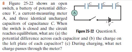
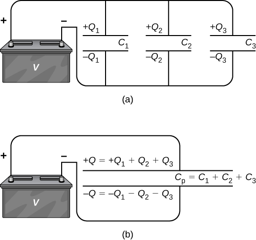
39 the diagram shows three capacitors an ideal battery and an open switch
Unanswered The diagram shows three capacitors, an ideal battery, and an open switch, S. The three capacitors all have the same capacitance. Energy stored in ... (6%) The diagram shows three capacitors, an ideal battery, and an open switch, S. The three capacitors all have the same capacitance (imagine 1.0 μ F, if you want a number). a) (3%) If switch S is closed, the charge on C 1 will: (Circle the correct choice.) INCREASE DECREASE REMAIN THE SAME
29 The circuit diagram shows a 4.0 Ω resistor and an 8.0 Ω resistor connected to a 6.0 V battery. 8.0 Ω 4.0 Ω 6.0 V What is the current in the 8.0 Ω resistor? A 0 A B 0.50 A C 0.75 A D 1.0 A 30 The diagram shows a circuit which includes an uncharged capacitor and a switch. X Y switch capacitor
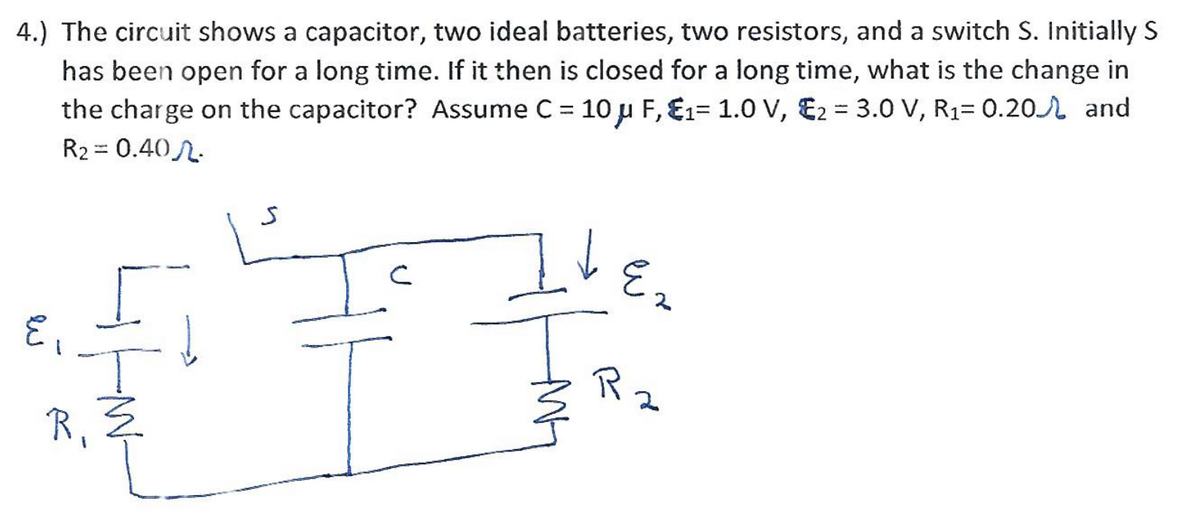
The diagram shows three capacitors an ideal battery and an open switch
Start studying Physics II Lab: quiz 1. Learn vocabulary, terms, and more with flashcards, games, and other study tools. 6. An inductance L and a resistance R are connected in series to an ideal battery. A switch in the circuit is closed at time 0, at which time the current is zero. The rate of increase of the energy stored in the inductor is a maximum: Solution: The current in the RL circuit is given by i= ./1 0 12 34 with τ=L/R. The energy stored in the Initially the switch is open. Sphere 1, with the larger radius, is given a positive charge. Sphere 2, with the smaller radius, is neutral. Then the switch is closed. Afterward, sphere 1 has charge Q1, is at potential V1, and the electric field strength at its surface is E1. The values for sphere 2 are Q2, V2, and E2.
The diagram shows three capacitors an ideal battery and an open switch. Problem 4: The diagram shows three capacitors, an ideal battery, and an open switch, S. The three capacitors all have the same capacitance. Determine what happens to the following quantities after the switch has been closed. Part (a) Equivalent capacitance of a circuit after the closing of switch S: MultipleChoice: 1) Increases 2) Decreases 3) Stays the same. The diagram shows three capacitors, an ideal battery, and an open switch, S. Capacitor 1 has capacitance C; capacitors 2 and 3 have capacitance 2C. Voltage ... Unanswered The diagram shows three capacitors, an ideal battery, and an open switch, S. The three capacitors all have the same capacitance. Question: (27%) Problem 4: The diagram shows three capacitors, an ideal battery, and an open switch, S. The three capacitors all have the same capacitance. Determine what happens to the following quantities after the switch has been closed co C2 29 子。. C3 Otheexperta.com A 11% Part (a) Equivalent capacitance of a circuit after the closing ...
An ideal battery is connected to three resistors and three capacitors as shown in the first diagram here (not to scale), with the switch initially open. This can be derived from a single 16 volt AC source with the aid of two diodes and two capacitors. Once again the diagram is much easier to comprehend that the text. To control each point, this time only a single pole change over locking switch is required. One terminal of the point motor is connected to the common earth and the other to the centre of the change over switch. The other two ... A diagram that shows a hierarchical classification of supercapacitors and capacitors of related types. A supercapacitor (SC), also called an ultracapacitor, is a high-capacity capacitor with a capacitance value much higher than other capacitors, but with lower voltage limits, that bridges the gap between electrolytic capacitors and rechargeable batteries. It typically stores 10 to 100 times ... 20.04.2015 · Battery Charger with Automatic Switch-off 71. 119. Earth Leakage Tester 71. 120. Controllable Electronic Load Circuit for DC Power Supply 72. 121. 16-Way Clap-Operated Swi tch …
Figure 2a shows the prototype of a BISC car. It features several BISC panels placed on the roof, behind the driver and passenger seats and inside the door and the bonnet. All these panels are connected in parallel. The BIC, battery and SC management systems, VCU and the motor controller are installed in the boot. The primary energy source, a Li ... Switch SW1 puts R20 in parallel with R21, reducing the value of the current-sense resistor combination, thus increasing the sensitivity of the meter. With SW1 closed, the full scale sensitivity of the ESR meter is one ohm. With it open, an ESR of five ohms is required to drive the meter to full scale. The gain of this stage is set by R17, R18, and R19. The latter is a 10K ohm trimmer ... An uncharged 30.0-µF capacitor is connected in series with a 25.0-Ω resistor, a DC battery, and an open switch. The battery has an internal resistance of 10.0 Ω and its open-circuit terminal voltage is 50.0 V. The leads have no appreciable resistance. At time t = 0, the switch is suddenly closed. The diagram shows three capacitors, an ideal battery, and an open switch, S. The three capacitors all have the same capacitance. Determine what happens to the following quantities after the switch has been closed. Variable Name Min Max Step Sample Value. 2/15/2018 The Expert TA ...
17.09.2021 · Also, the switch commonly referred to as "switch 33" on a Bally or Stern CPU board, and used to reset audits and bookkeeping, is not part of the switch matrix either. This switch receives a signal from the 6800 CPU chip, and when closed, sends the signal to ground. Starting with the first MPU-200 Stern game, Meteor, Stern added a second switch to the inside of the coin door to serve the ...
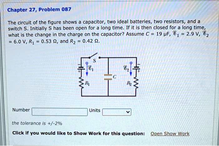
Solved Chapter 27 Problem 087 The Circuit Of The Figure Shows Capacitor Two Ideal Batteries Two Resistors And A Switch S Initially Has Been Open For A Long Time If It
b=0 because the battery and capacitor are in series. C Physics 102: Lecture 7, Slide 8 •KLR:E – 0 – q∞/C = 0 ⇒q∞ = E C. Discharging Capacitors Time to use that stored energy! • Capacitor is initially charged (Q) d it h i(Q) and switch is open. Switch is then closed. • What is current I
Rc circuit problems pdf
Tantalum electrolytic capacitors as discrete components are not ideal capacitors, as they have losses and parasitic inductive parts. All properties can be defined and specified by a series equivalent circuit composed of an idealized capacitance and additional electrical components which model all losses and inductive parameters of a capacitor. In this series-equivalent circuit the electrical ...
Transcribed image text: (7%) Problem 14: The diagram shows three capacitors, an ideal battery, and an open switch, S. The three capacitors all have the same ...
14% Part (g) Calculate the numerical value of Uinju. (14%) Problem 5: The diagram shows three capacitors, an ideal battery, and an open switch, S. The three ...
The student uses a switch to charge and discharge the capacitor using the circuit shown. The ammeter is ideal. The emf of the battery is 12 V. The resistor R in the circuit has a resistance of 1.2 kΩ. Calculate the time taken for the charge on the capacitor to fall to 50 % of its fully charged value. [3 marks]
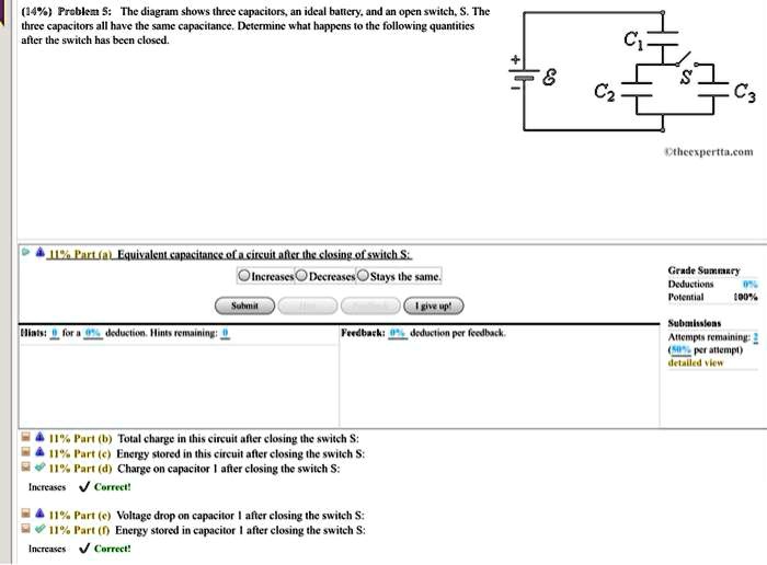
Solved 14 Prabkz The Diagram Shows Three Capacitons Ideal Ballcry And Open Swilch Capacitors All Have The Sme Capacitalce Detemmil What Happens Thc Following Quantities Alter Thc Swlch Has Bren Closcd Cz C3
Three point charges lie at the vertices of an equilateral triangle as shown. All three charges have the same magnitude, but charges #1 and #2 are positive (+q) and charge #3 is negative (-q). The net electric force that charges #2 and #3 exert on charge #1 is in A. the +x-direction. B. the -x-direction. C. the +y-direction. D. the -y-direction.
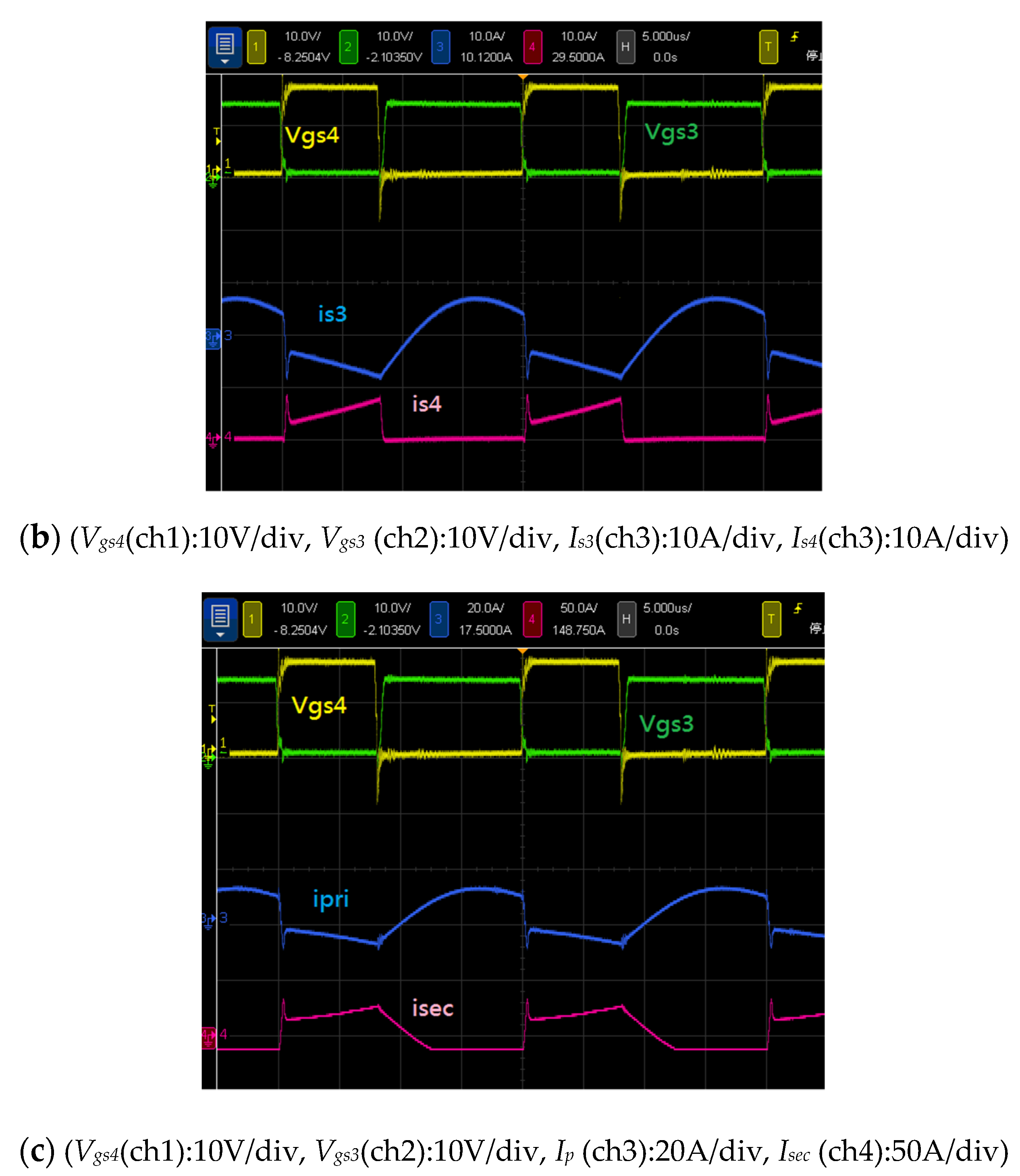
Sustainability Free Full Text Novel High Efficiency Three Port Bidirectional Step Up Step Down Dc Dc Converter For Photovoltaic Systems Html
Transcribed image text: (8%) Problem 7: The diagram shows three capacitors, an ideal battery, and an open switch, S. The three capacitors all have the same ...
Answer to A)The diagram shows three capacitors, an ideal battery, and an open switch, S . Capacitor 1 has capacitance C; capacitors 2 and 3 have ...1 answer · Top answer: Answers : Part ( a ) Answer : The charge of capacitor 2 before closing the switch : (2/3)CV Part ( b ) Answer : The charge on the capacitor 2 after closing ...

2 Figure Shows Three Circuits Each Consisting Of A Switch And Two Capacitors Initially Charged As Indicated After The Switch Has Been Closed In Which Circuit If Any Will The Charges
Initially the switch is open. Sphere 1, with the larger radius, is given a positive charge. Sphere 2, with the smaller radius, is neutral. Then the switch is closed. Afterward, sphere 1 has charge Q1, is at potential V1, and the electric field strength at its surface is E1. The values for sphere 2 are Q2, V2, and E2.
6. An inductance L and a resistance R are connected in series to an ideal battery. A switch in the circuit is closed at time 0, at which time the current is zero. The rate of increase of the energy stored in the inductor is a maximum: Solution: The current in the RL circuit is given by i= ./1 0 12 34 with τ=L/R. The energy stored in the
Start studying Physics II Lab: quiz 1. Learn vocabulary, terms, and more with flashcards, games, and other study tools.

Figure Shows An Ideal Battery Connected To A Resistor And Capacitor The Value Of Resistance In 2 Is Given As R Kq2 Kq K Where K 1 Q

On Board Electric Vehicle Battery Charger With Improved Power Quality And Reduced Switching Stress Gupta 2020 Iet Power Electronics Wiley Online Library

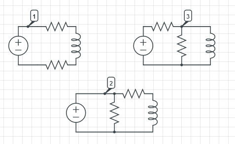
The Figure Shows Three Circuits With Identical Batteries Inductors And Resistance Rank The Circuits According To The Currents Through The Battery Just After The Switch Is Closed Greatest First Img Src Https D10lpgp6xz60nq Cloudfront Net
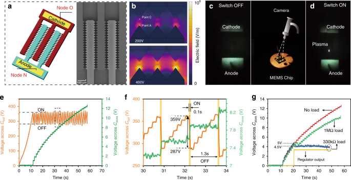
Employing A Mems Plasma Switch For Conditioning High Voltage Kinetic Energy Harvesters Nature Communications

Sustainability Free Full Text Novel High Efficiency Three Port Bidirectional Step Up Step Down Dc Dc Converter For Photovoltaic Systems Html
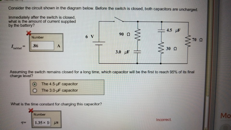

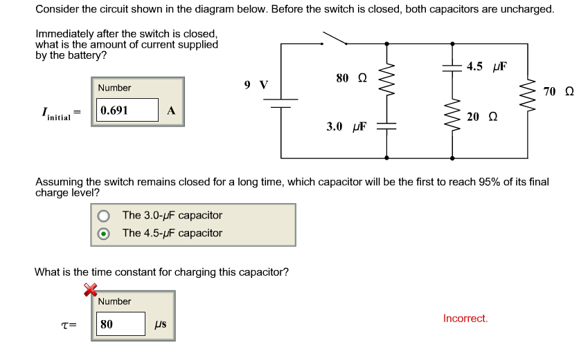


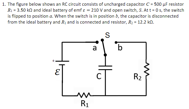





0 Response to "39 the diagram shows three capacitors an ideal battery and an open switch"
Post a Comment