39 commercial defrost timer wiring diagram
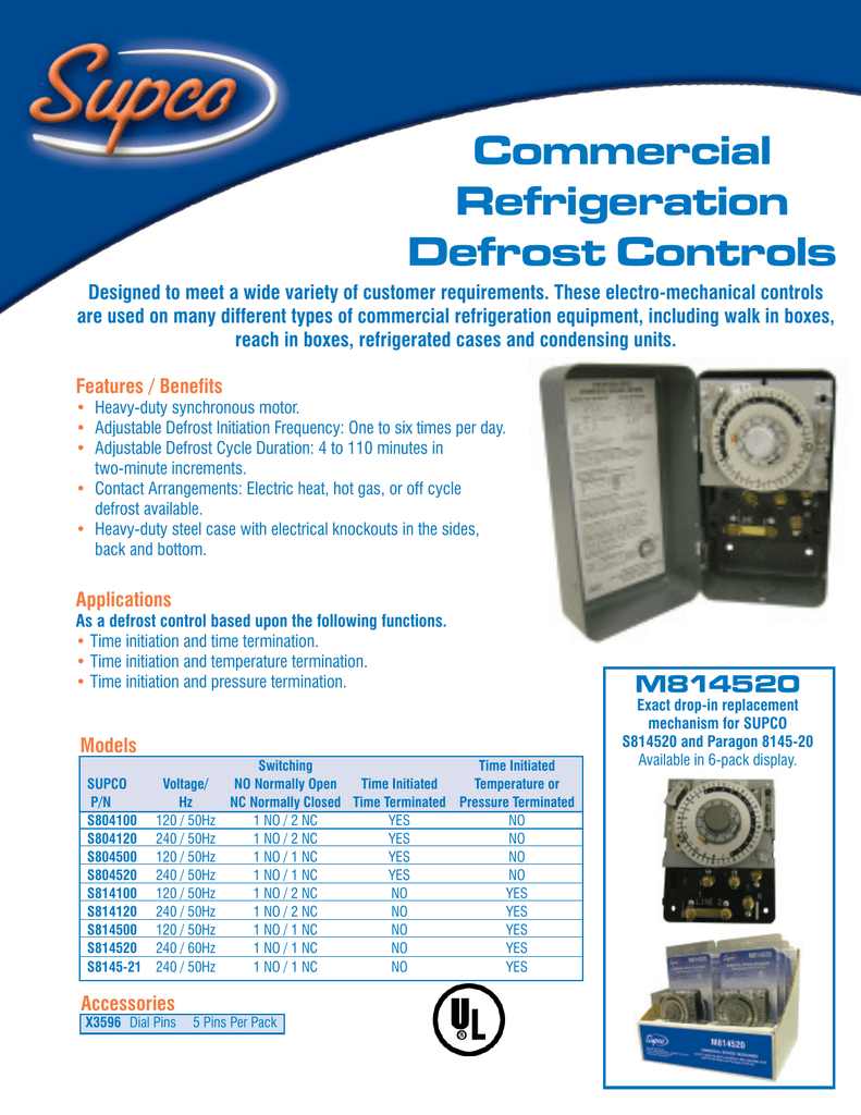
Wiring Diagram. Models , and E -. the wiring diagram chosen. (Default setting B). 14 AWG OR LARGER WIRES RATED AT LEAST ⁰C. LISTED . and Electric Heat. •. •. •. Series Specifications. Uni-Line Applications and Wiring Diagrams. MECHANICAL.Paragon - V Defrost Timer - Designed for commercial freezers and refrigerators, Paragon commercial ... Commercial Refrigeration Defrost Controls ... Normally closed thermostat used with defrost heater. Wiring using 120V or 240V single phase line compressor voltage common to timer. CYCLE LIMIT SWITCH HEATER COMP THERMOSTAT Wiring Diagrams Electric Heat Defrosting S8141 & S8145 Series Wiring Diagrams Electric Heat Defrosting S8041 & S8045 Series ...
timer only advances when the compressor is running. After the timer measures an accumulated run time equal to a predetermined amount, the system will enter into the defrost cycle. This type of defrost is often referred to as a cumulative run-time defrost. Even the cumulative defrost systems fail to account for the number of times the door is opened

Commercial defrost timer wiring diagram
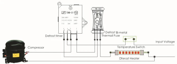
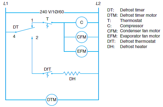
In this video you can learn about the defrost timer wiring diagram of a frost free refrigerator and circuit diagram Step by step details about the function o... paragon defrost timer 8145 20 wiring diagram - paragon defrost timer wiring furthermore paragon defrost timer 8145 rh beinclover co. File Type: JPG. Source: 140.82.51.249. paragon defrost timer 8145 20 wiring diagram - refrigerator defrost timer wiring diagram Download Paragon Time Clock Wiring Diagram Lukaszmira Best Timer Defrost. The defrost timer is operated by a single-phase synchronous motor like those used to operate electric wall clocks, Figure 28-1. The contacts are operated by a cam that is gear driven by the clock motor. A schematic drawing of the timer is shown in Figure 28-2. Notice that terminal 1 is connected to the common of a single-pole double-throw ...
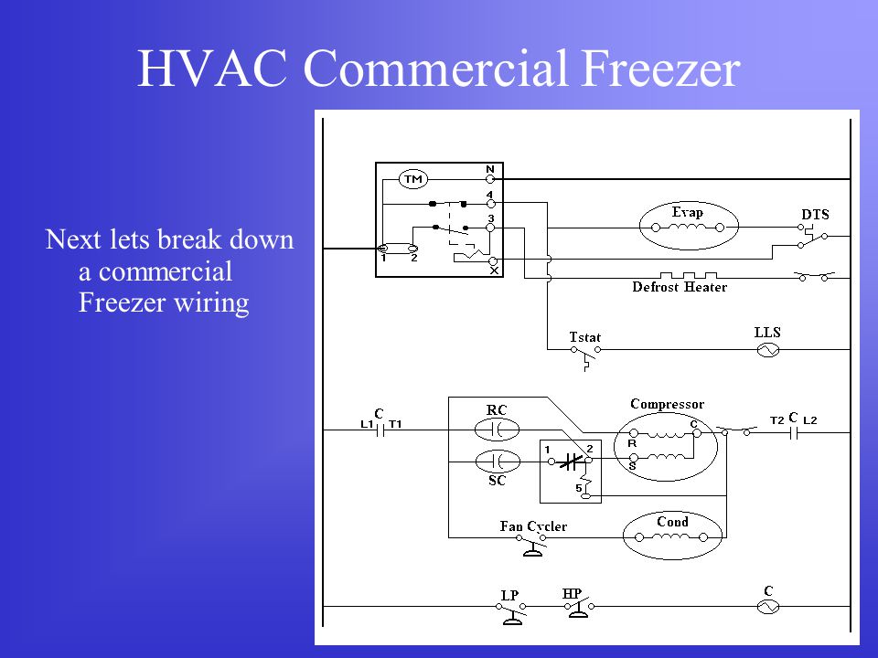
Commercial defrost timer wiring diagram. As well as the automatic defrost function, a manual defrost can be enabled, if the temperature conditions allow, by pressing the" button for more than 5 seconds. Wires NWhite Neutral XPurple defrost termination This info obtained from sheet included with the Grasslin. 4tors Paragon Commercial Defrost For Electric Heat Hot Gas or Compressor Shutdown Defrosting Bracket and 50 Hz available Applications and Wiring Diagrams MECHANICAL DEFROST TIMER Series. Wiring 220V Commercial Freezer Defrost Timer with Walk In Freezer Defrost Timer Wiring Diagram, image size 598 X 452 px, and to view image details please click the image.. The most common form of defrosting a freezer's unit cooler is done by control for the evaporator is wired to terminal "X" on the Wiring for a single evap freezer system or reach in freezer. Any questions or comments Feel free to ask in the comment section . Thanks for watching 👍. ...
Commercial Defrost Timer Wiring Diagram from schematron.org Effectively read a cabling diagram, one has to know how typically the components inside the method operate. For instance , if a module is powered up and it sends out the signal of fifty percent the voltage in addition to the technician would not know this, he'd think he provides an ... Wiring Diagram - Freezer ½ to 2 HP Single Phase. .. Set the correct time of day on the defrost timer. Do not set a cooler thermostat below the walk-ins design temperature or product Diagram 9 - Typical Wiring Diagram for Single with Defrost Timer Only.Jul 02, · I can increase the defrost time (Grasslin timer), but don't believe it will be ... Defrost timer also shuts off evap fans and energizes defrost heaters. Evap has termination stat to shut off heaters if they get too hot and often kick defrost timer out on the X terminal. Fans are wired though same little 3 wire stat and won't come on till evap gets cold again after defrost. The Latest Paragon® Defrost Timer • Universal Defrost Timers (UDT) • Works with multiple voltages • Removes built up of ice and frost • Easy to install • Simple to program • Part 9145-00 temp terminated • Part 9045-00 time terminated • Available as mechanism only without case - Add "M" to end of part number
Defrost Control Board Wiring Diagram - wiring diagram is a simplified welcome pictorial representation of an electrical circuit. It shows the components of the circuit as simplified shapes, and the facility and signal connections in the middle of the devices. A wiring diagram usually gives counsel practically the relative direction and ... Description: Commercial Defrost Timer Wiring Diagram Paragon Defrost Timer regarding Defrost Clock Wiring Diagram, image size 476 X 332 px, and to view image details please click the image.. Here is a picture gallery about defrost clock wiring diagram complete with the description of the image, please find the image you need. The Paragon® Series Auto Voltage Defrost Timer is designed competitive voltage-specific mechanical defrost timers, eliminating Wiring Diagrams. Simple wiring. Resources: Paragon sell sheet shows model numbers and wirings diagrams, Replace with TT or CT series. Post tagged: bohn walk in freezer wiring diagram, commercial walk in freezer wiring diagram, heatcraft walk in freezer wiring diagram, kolpak walk in freezer wiring. Jul 01, · I am trying to install a defrost timer on a commercial freezer. It is a defrost-o-matic replacement. I have it so that the compressor starts and stops ok but can not ...
If not, probably the wiring is backwards. They generally are good timers. If it has, you may have. how to wire model defrost timer - Paragon Defrost Timer Changing the defrost timer will not require use of a wiring diagram. Results 1 - 37 of 37 The Paragon® Series Auto Voltage Defrost Timer is designed for commercial freezers and refrigerators.
I am trying to install a defrost timer on a commercial freezer. It is a 220 defrost-o-matic replacement. I have it so that the compressor starts and stops ok but can not figure out how or maybe I should say where to hook up the defrost heater. Could you sketch me a simplified wiring diagram and tell me how to test to make sure it is right.
Description: Freezer Defrost Timer Wiring 220V Commercial Freezer Defrost Timer with Walk In Freezer Defrost Timer Wiring Diagram, image size 598 X 452 px, and to view image details please click the image.. Here is a picture gallery about walk in freezer defrost timer wiring diagram complete with the description of the image, please find the image you need.
Commercial refrigeration wiring diagrams. Walk in freezer wiring diagram. Retail store walk in coolers and freezers boiler operating control used as a thermostat universal defrost timer wiring. Wiring diagram a schematic drawing of the wiring of an electrical system.
How To Bypass Basic Timer Defrost Applianceblog Repair Forums. Grasslin dtmv40 series operating defrost time controls hvac r intermatic dtav40 installation 25 commercial timer wiring required snaps into existing enclosures t 49f diagram swapping on auto product catalog pages 101 multi voltage 40 the instructions for true part 831993 how to test a fridge control dcne heatcraft dtsz bypass basic ...
Designed for commercial freezers and . Applications and Wiring Diagrams. MECHANICAL. DEFROST. TIMER. Nov 14, · Defrost Timer Whirlpool Refrigerator Location - here you are at our site, this is images about defrost timer whirlpool refrigerator location posted by Benson Fannie in Wiring category on Nov 14, You can also find other images like ...
Refrigerator Defrost Timer Wiring Diagram Collection. refrigerator defrost timer wiring diagram - A Beginner s Overview of Circuit Diagrams A very first look at a circuit diagram may be confusing, however if you can check out a train map, you can review schematics. The function is the same: getting from factor A to point B. Literally,…
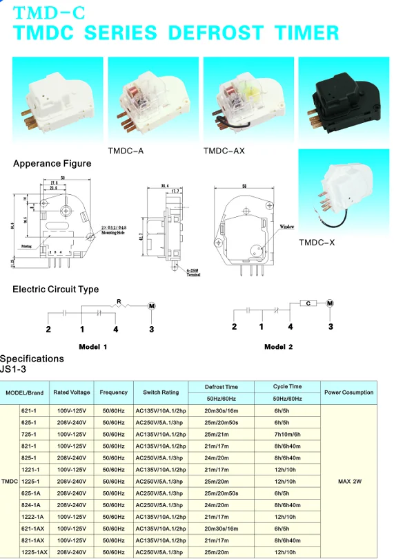
1 3hp 110 120v 50 60hz Commercial Electronic Refrigertor Defrost Timer 6 Hours 25 Minutes For Refrigerator And Freezer View 110v Defrost Timer Icecool Oem Product Details From Guangzhou Icecool Refrigeration Equipment Co Ltd On
EDT10--ELECTRONIC DEFROST TIMER 120V / 10A. The EDT Series defrost timers utilize adjustable timing and industry standard wiring to replace most domestic and many commercial defrost timers. Features/Benefits. Electronic circuitry; Universal replacement; Humidity range: 10-95% Non-condensing; Temperature range: 32°F to 135°F (0°C to 57°C ...
This timer is not the primary means of terminating defrost, but acts as a back-up should the primary defrost termination device fail. This back-up defrost termination is usually set for 20 minutes. *Please refer to your specific timer's wiring diagram as different manufacturers may use different terminals than this example.
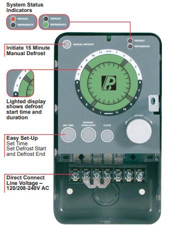
2. Set Defrost Insert pin(s) to desired defrost time(s) on outer dial. 3. Set Defrost Duration Move copper pointer to desired duration of defrost time on inner dial. Install our Commercial Defrost Controls today to understand why Paragon® is Simply the Right Choice™ in Defrost Timers. An ISO 9001 - 2008 Certified Company 1 Year Limited ...
Ge Defrost Timer Wiring Diagram - wiring diagram is a simplified welcome pictorial representation of an electrical circuit. It shows the components of the circuit as simplified shapes, and the knack and signal connections amongst the devices. A wiring diagram usually gives information virtually the relative aim and conformity of devices and ...
The defrost timer is operated by a single-phase synchronous motor like those used to operate electric wall clocks, Figure 28-1. The contacts are operated by a cam that is gear driven by the clock motor. A schematic drawing of the timer is shown in Figure 28-2. Notice that terminal 1 is connected to the common of a single-pole double-throw ...
paragon defrost timer 8145 20 wiring diagram - paragon defrost timer wiring furthermore paragon defrost timer 8145 rh beinclover co. File Type: JPG. Source: 140.82.51.249. paragon defrost timer 8145 20 wiring diagram - refrigerator defrost timer wiring diagram Download Paragon Time Clock Wiring Diagram Lukaszmira Best Timer Defrost.
In this video you can learn about the defrost timer wiring diagram of a frost free refrigerator and circuit diagram Step by step details about the function o...






0 Response to "39 commercial defrost timer wiring diagram"
Post a Comment