39 3 way mixing valve piping diagram
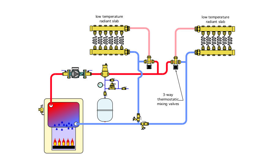
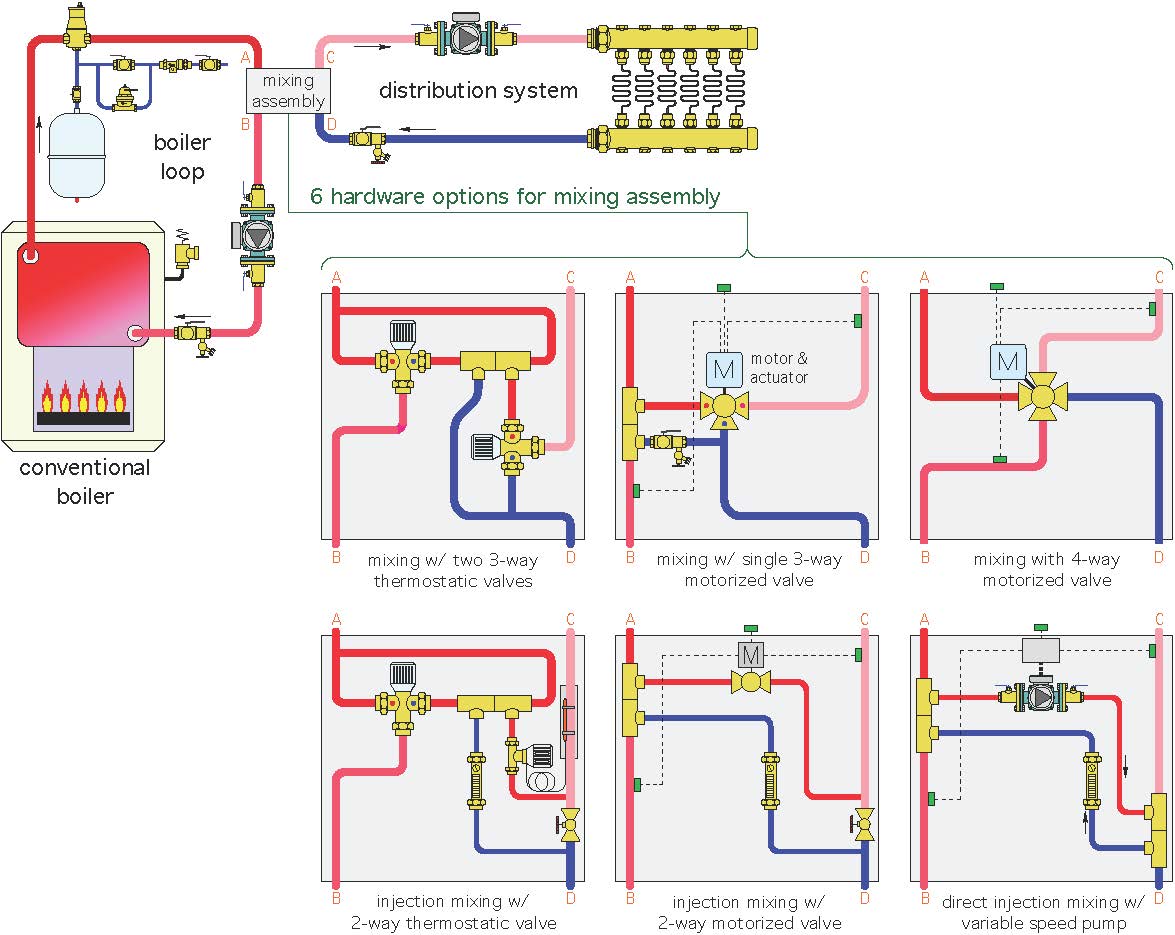
Check that inlet and outlet of 2-way valves are correct; check that the “A”, “B”, and “AB” ports of three-way valves are piped correctly. Flow direction arrows must be correct. 3. Blow out all piping and thoroughly clean before valve installation. 4. Clean male pipe threads with wire brush and rag. If threads have been damaged Piping for 3-way motorized mixing valves ... The diagrams presented in idronics are conceptual, and do not represent complete schematics for any specific ...80 pages
be a “by-pass” application of a three-way valve. Naturally, the piping method chosen will depend on what type of valve body is specified. Normally, a mixing ...8 pages
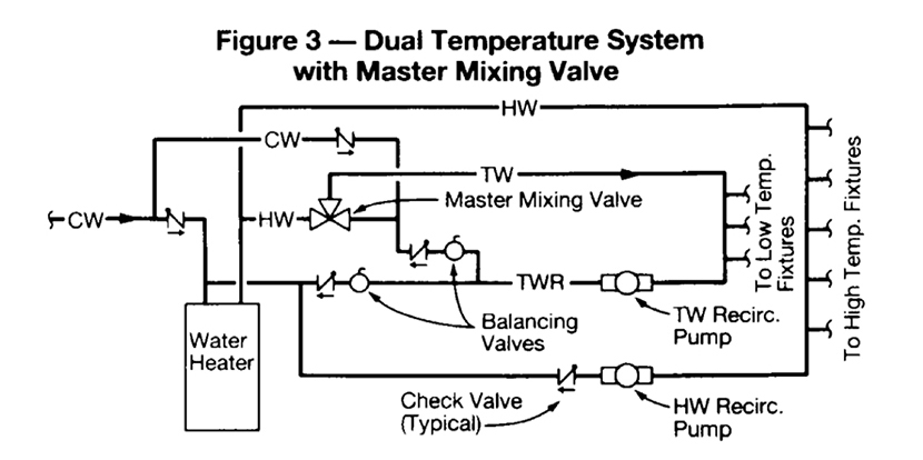
3 way mixing valve piping diagram
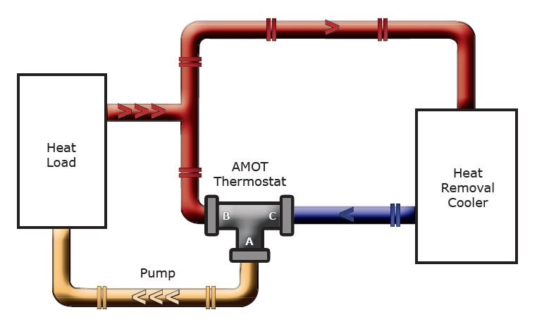
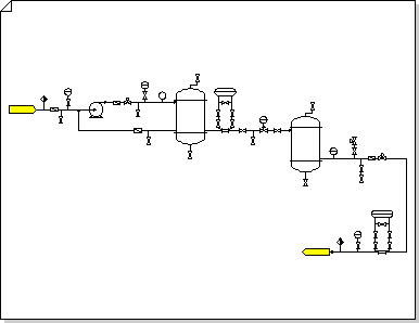
Mixing and diverting three-way valves are shown in Figures 1. In a mixing valve, two incoming streams are combined into one outgoing stream. The valve body can install in any position and orientation. Piping diagram 3 way valve is a diagram picture through the fungsional through the piping instrumentation and tract instrumentation constituent used in the area through the instrument technical plan. V5013bcf three way mixing and diverting valves 60 21294 from. Not sure which piping diagram to choose? Call Leonard Valve today at (800)-222-1208or watch our recirculation video under videos.
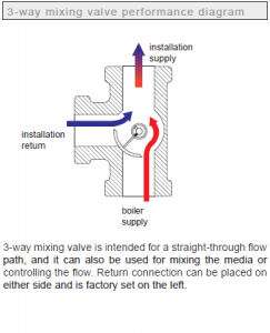
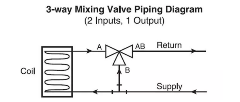
3 way mixing valve piping diagram. Three-way Mixing Valve Installation Guide 1 Introduction The Uponor Three-way Mixing Valve (A3040075, A3040100) is a microprocessor-controlled valve designed to regulate the supply water temperature to a radiant heating system by modulating the position of the valve. Mixed supply setpoint can be configured to reset from the outdoor air temperature. Belimo 3 way valve piping diagram. The actuators are controlled by a standard voltage for onoff modulating or floating point control which moves the ball valve to the position dictated by the control system. Looping line make conjunction at the process pipe diagram. Piping diagram 3 way valve is a diagram picture through the fungsional through ... 3 WAY - V321 MIXING VALVE BODY The mixing valve body is installed on the return side of the coil. The water diverts in the “T” and mixes in the valve. Piping example No1: The flow enters port A from the coil and port B from the bypass and exits from the common port AB STEM UP: FLOW B-AB STEM DOWN: FLOW A-AB 3-Way Valve Flow Rate for Water Applications (Gallons Per Minute, GPM). Cv .. y Mixing Valve Piping Diagra Three-Way Diverting Valve Piping Diagram. schematron.org Dimensions diagram for 2-way and 3-way globe valves. 6 Installation in the supply or return is dependent on the selected hydraulic circuit.
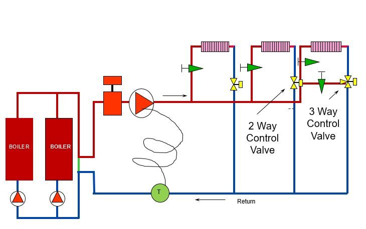
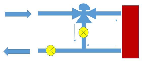
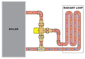
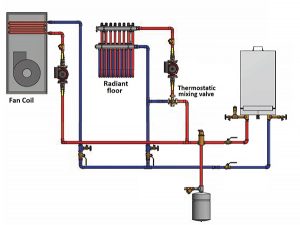
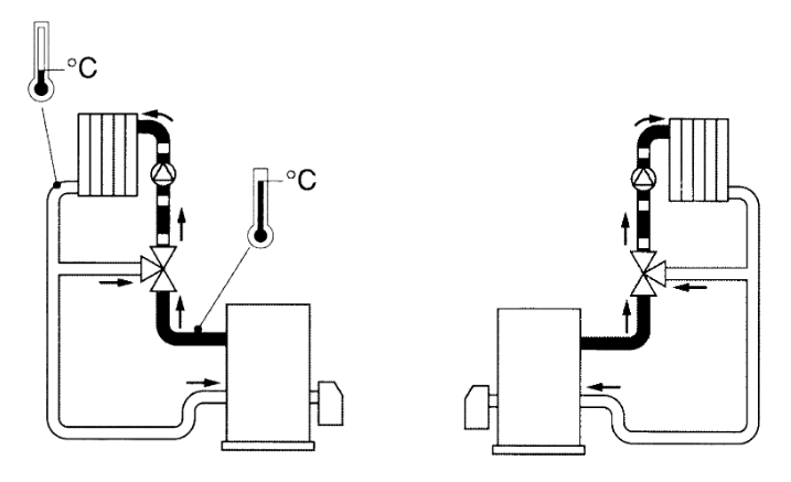
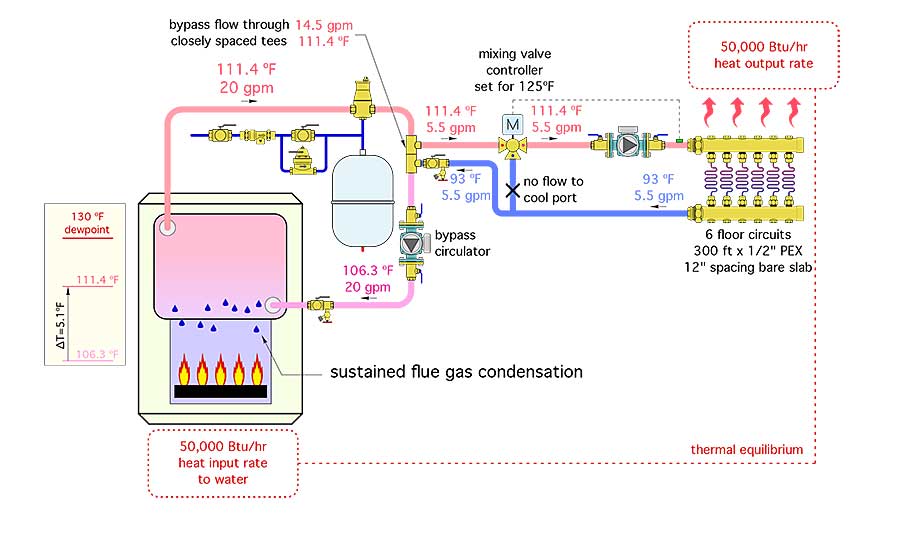
Fig. 8. Three-way mixing valve operation–coil bypass. Three-way valves maintain constant flow in the piping. As the temperature requirements change, the volume of the fluid in the coil varies. AB A B M11761 HEATING COIL FULL HEAT 5 GPM 5 GPM 2.5 GPM 5 GAL./MIN. AB A B PROPORTIONED HEAT 2.5 GPM SUPPLY MAIN RETURN MAIN 5 GPM 5 GPM AB A B NO ... Piping and piping junctions f. Valves 1.12 Given a fluid power type drawing, ... Engineering Fluid Diagrams and Prints Page 3 Valve Symbols Valves are used to control the direction, flow rate, and pressure of fluids. Figure 1 ... 3-way valve in the air supply line. The 3-way valve may A mixing valve can also be used in a bypass application to control the flow through the coil by placing the valve downstream of the coil. The flow through the coil is still controlled by the stem position of the mixing valve. The location of the three-way valve will not affect the operation of the system. In both scenarios, the valves are 1 Apr 2003 — Tips for properly installing these mixing valves in radiant ... The proper piping of a three-way thermostat valve is shown in Figure 1.
Three-way valve with chrome plated brass ball and nickel plated stem and NPT female ends ... Three-Way Mixing Valve Piping Diagram. (2 Inputs, 1 Output). 1.9) can ideally prescribe a mass flow rate, conventional throttle valves are not necessary for a system setup. Parameters, Three-way valve type (distribution/ ... Not sure which piping diagram to choose? Call Leonard Valve today at (800)-222-1208or watch our recirculation video under videos. The valve body can install in any position and orientation. Piping diagram 3 way valve is a diagram picture through the fungsional through the piping instrumentation and tract instrumentation constituent used in the area through the instrument technical plan. V5013bcf three way mixing and diverting valves 60 21294 from.
Mixing and diverting three-way valves are shown in Figures 1. In a mixing valve, two incoming streams are combined into one outgoing stream.
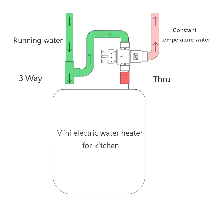
Floor Heating System Thermostatic Mixing Valve Dn20s Buy Thermsotatic Mixing Valve Thermostatic Valve Mixing Valve Product On Alibaba Com











0 Response to "39 3 way mixing valve piping diagram"
Post a Comment