37 holley hp efi wiring diagram
This manual contains information and diagrams related to wiring most Holley EFI products including ECU's, ignition systems, nitrous systems, water/methanol injection systems, sensors, and more. 1.1 Important Wiring "Do's and Don'ts" An EFI system depends heavily on being supplied a clean and constant voltage source. NOTE: See section 20.0 for applications and diagrams on wiring most ignition systems. 18.0 LOOSE WIRES. The following loose wires in the main wiring harness ...26 pages
HP EFI. Holley's HP EFI is one of the most capable standalone ECUs available today. Every parameter of your engine's tune can be modified via Holley's easy-to-use EFI software. The lb/hr fueling strategy is an industry first, making changes on the fly that much easier. Those features are just the beginning of the HP ECUs capabilities though ...

Holley hp efi wiring diagram
HP/Holley Dual Sync/MSD 6AL-2 Combo Wiring Diagram? On my 'scratch-build' (no OEM stuff) E85 powered, N/A big block Ford street rod with the Holley HP ECU (554-113), I'm using the Holley 558-508 main harness, Holley 565-210 Dual Sync distributor, and sensor numbers 554-101, 534-20, 534-10, 554-102, 554-103. Also using MSD 6421 6AL-2 & MSD 8253 ... WIRING MANUAL & DIAGRAMS 199R10555 HP EFI and Dominator EFI Systems ... Holley offers a USB cable with a sealed connector, PN 558-409 for applications were the USB cable will be plugged in, and the ECU is mounted in a dirty environment. HP ECU - The HP ECU has two main connectors: Holley Hp Efi Wiring Diagram from www.efisystempro.com Effectively read a cabling diagram, one provides to find out how the components in the system operate. For instance , when a module is usually powered up and it also sends out a new signal of fifty percent the voltage in addition to the technician does not know this, he would think he ...
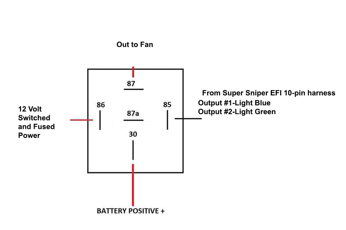
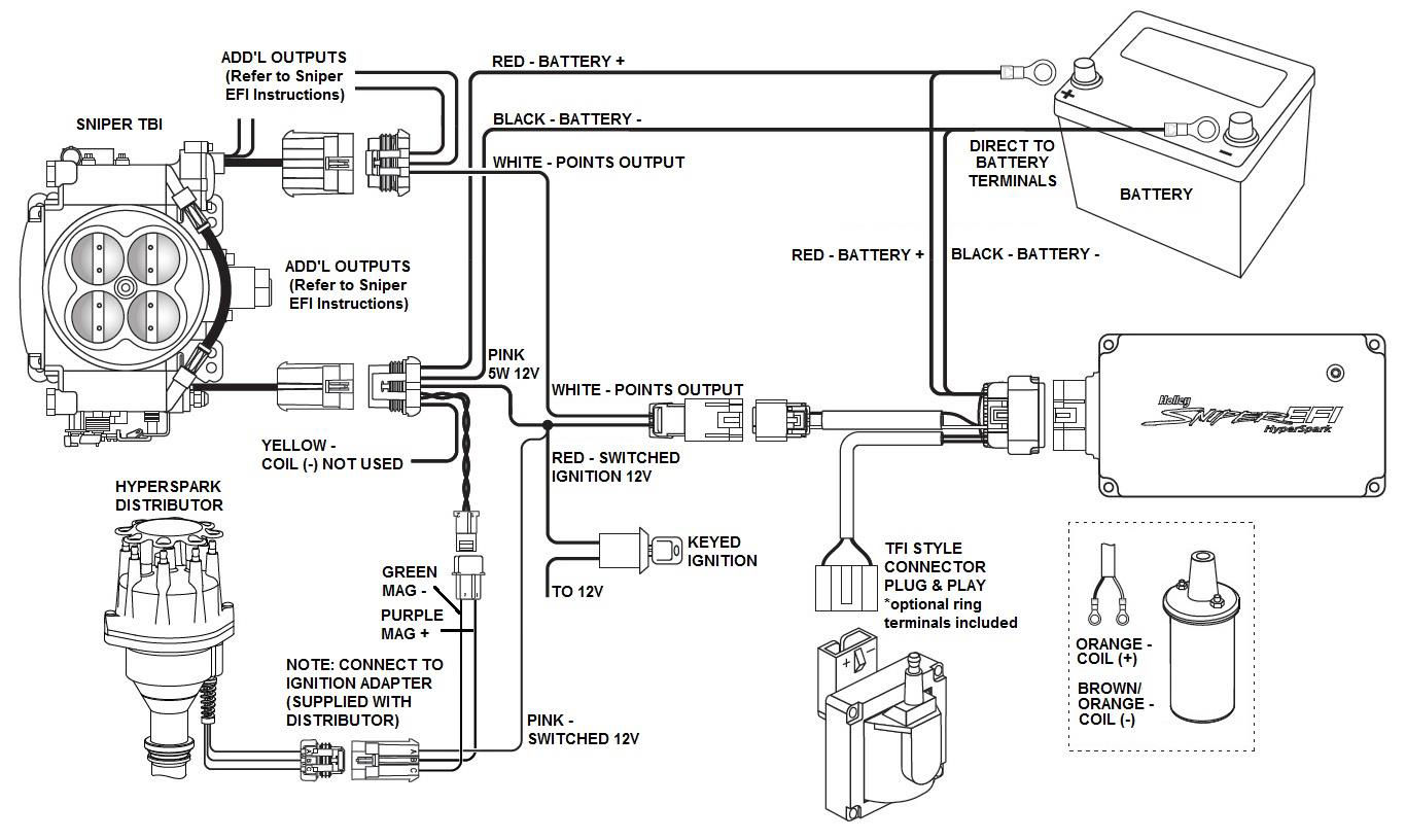
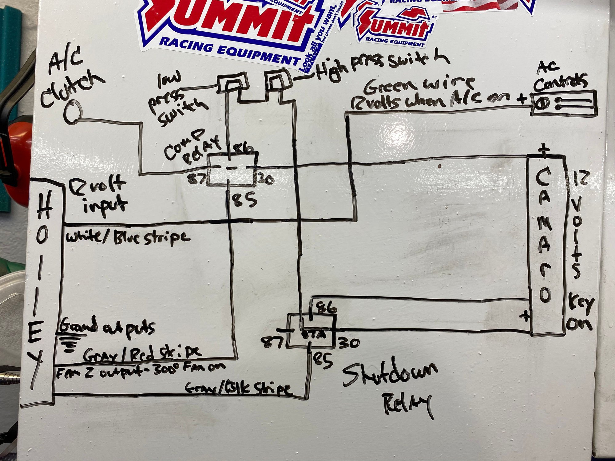
Holley hp efi wiring diagram. Holley has written this manual for the installation of the HP EFI ... NOTE: See section 18.0 for applications and diagrams on wiring most ignition systems.27 pages https://www.holley.com/brands/holley_efi/ HYPERSPARK WIRING DIAGRAM: TROUBLESHOOTING: Every HyperSpark EFI Ignition undergoes numerous quality control checks including a four hour burn-in test. If you experience a problem with your ignition, our research has shown that the majority of problems are due to improper installation or poor connections. Hello. Last week I bough HP EFI 550-603N, and I would like to have the wiring diagram that helps me to connect two electric fans. Also, how to connect a switch that I can change between 2 RPM "cutout 6000 rpm & 7000 rpm"? Is there a software that works with a MAC laptop? Thanks.
Holley Hp Efi Wiring Diagram. To properly read a wiring diagram, one has to know how typically the components in the system operate. For example , in case a module will be powered up and it also sends out the signal of 50 percent the voltage plus the technician would not know this, he'd think he provides a problem, as this individual would ... LS2/3/7+ (58x/4x) Engine Main Harness for HP EFI & Dominator EFI. Part # 558-103 Be the first to write a ... Click here to find the Holley EFI dealer in your area! Wiring Shop Quick Reference Guide Wiring Shop Quick Reference Guide. Instructions for 558-103. EFI selection chart. Wiring Diagram. Reviews. Be the first to write a review. Write a ... Holley Hp Efi Ls1 Wiring Diagram - wiring diagram is a simplified within acceptable limits pictorial representation of an electrical circuit. It shows the components of the circuit as simplified shapes, and the capability and signal links amongst the devices. A wiring diagram usually gives guidance about the relative face and treaty of ... Madcomics Holley Hp Efi Wiring Diagram I bought the Holley dual sync distributor. I don't find any diagram that shows what wire does what, and where it should go on the ignition plug. Back to Holley . Advanced Search. BBK 80mm T/B, Holley Dominator MPFI & DIS, 36-1 crank trigger, 1x cam sync, 200A 3G alternator, Optima Red battery, R134a A/C ...
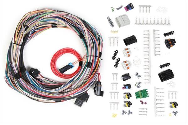
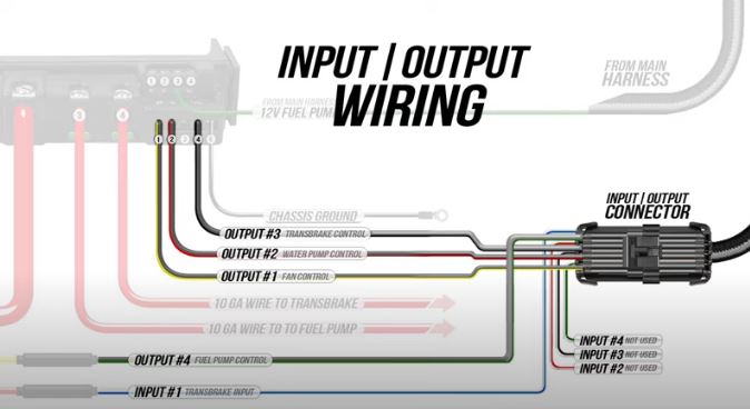
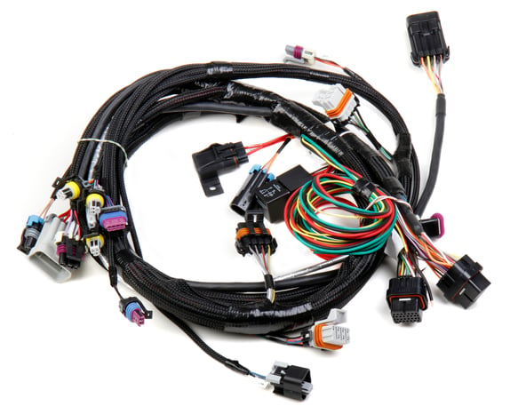
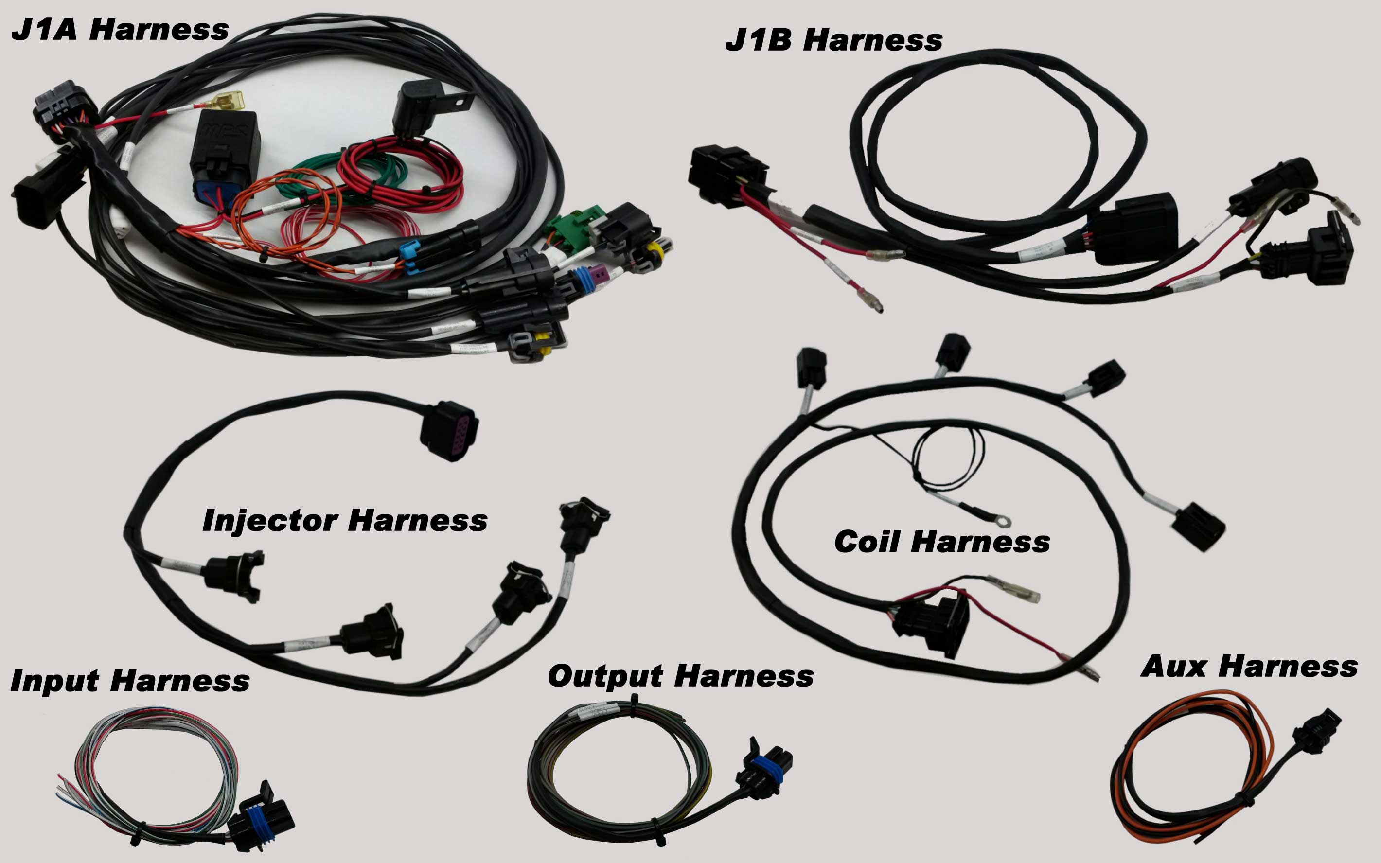
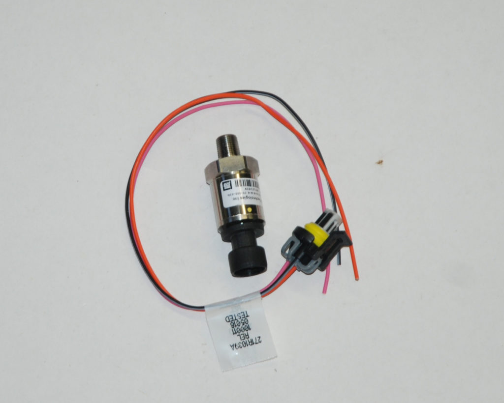
This harness connects to the 8 pin Metripak Input/Output connector, located in most Holley EFI main harnesses (Terminator harness have a 3 pin I/O connector). The following indicates what ECU pin that the specific wires are connected to, and the type of input or output it can be configured as. Wire Color Type Can be Configured As Holley EFI wiring harnesses are used with Holley's Avenger, HP, Terminator, and Dominator EFI Systems. EFI harnesses for various Holley systems can consist of the main harness, transmission harness (if applicable), injector harness, ignition/coil harness, throttle body harness, and auxiliary harnesses to access features of your Holley EFI system. Holley's Avenger and Dominator series share the same harness. This video goes through a wire-by-wire description of the system to take away some of the "scar... Holley EFI now offers a "flying lead" harness featuring pre-terminated J1A and J1B connectors. With 15 feet of wire, you can place sensors, connectors and more wherever you need! 15' long flying lead harness, allows you to completely customize your main harness installation. 60 Holley Crimped Wires (57x 20 ga, 3x 18 ga).
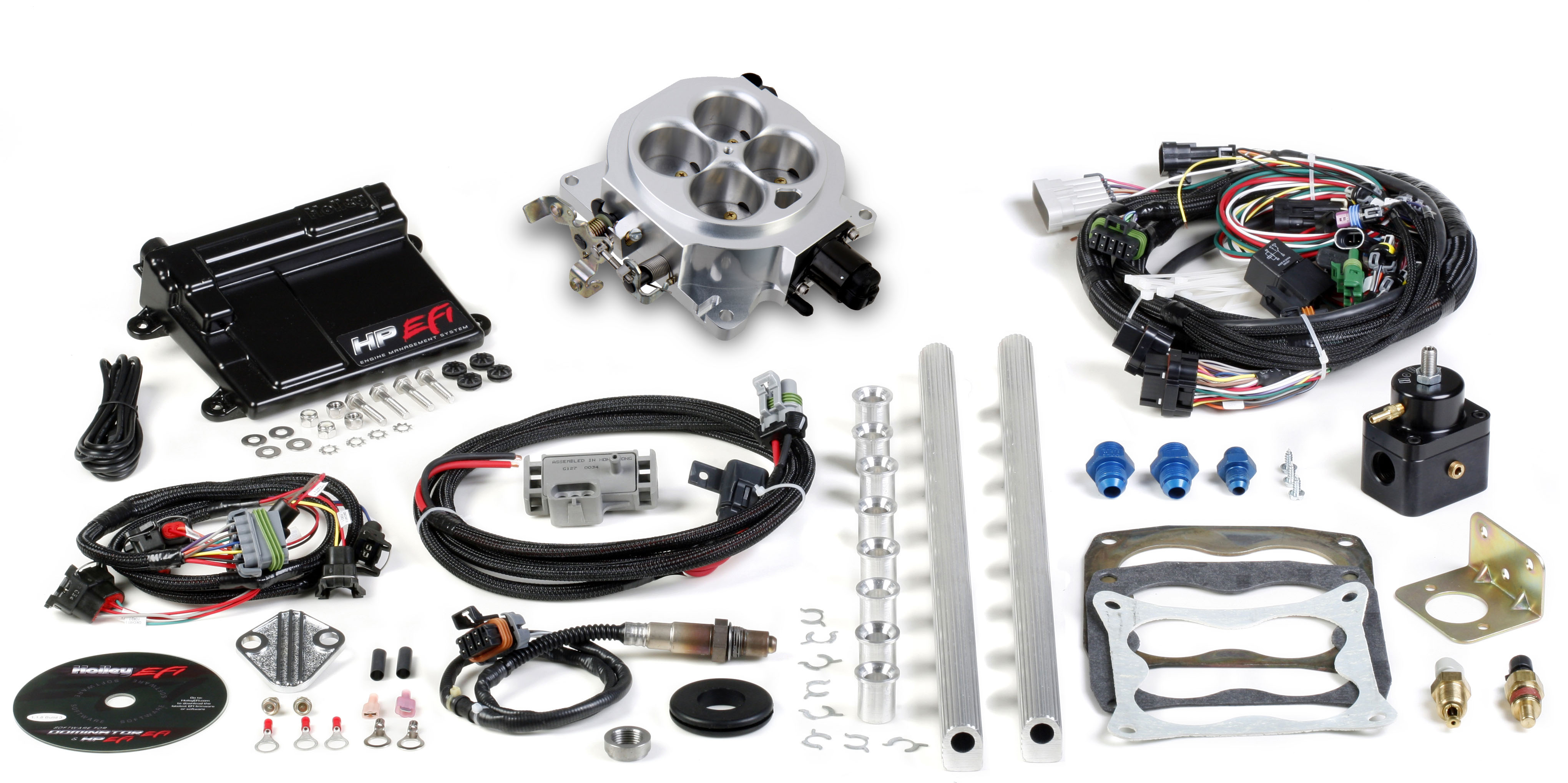
Holley Hp Efi 550 603n Ecu Amp Harness Kit For Ls Engine Ls2 Ls3 Ls7 58x Mpfi Ev6 Ebay The Gen III controller (LS1a) started in the 1997 Corvette and found its way into the 1998 Corvette and Camaro. GM revised the ECM in 1999 (LS1b) with a newly-designed case and updated circuitry.
Holley has been the undisputed leader in fuel systems for over 100 years. Holley carburetors have powered every NASCAR® Sprint® Cup team and nearly every NHRA® Pro-Stock champion for four decades. Now, Holley EFI is dominating the performance world as well as our products for GM's LS engine.
2 INTRODUCTION & SYSTEM REQUIREMENTS Holley Performance Products has written this manual for the installation of the Sniper EFI TBI fuel injection system. This basic manual contains the information necessary for the installation of the throttle body, wiring, and sensors.
LS1/6 Main Harness for HP EFI & Dominator EFI ... Holley is the new standard in EFI! Whether you're engine swapping ... Wiring Shop Quick Reference Guide$481.95 · In stock
3 1.0 OVERVIEW The HP EFI Universal Retrofit Kits (P/N 550-500 & 550-501) are designed for engines that have no off-the-shelf port fuel injection manifold available. It comes with almost all the components necessary for complete installation. Other components
Apr 18, 2020 — Holley Hp Efi Plug And Play Ecu And Harness Kit For Gm Ls2 Ls3 Ls7 Ntk O2 Sensor. Holley Efi Ecu Mounting Wiring. Hp Efi Ecu Harness Kits ...
NOTE: The Holley DOMINATOR fuel pump utilizes o-ring sealed will need Holley Fuel pump relay kit P/N 30 AMP x 2 if wiring pumps. HP EFI and Dominator EFI Important Wiring "Do's and Don'ts". .. contains information and diagrams related to wiring most Holley EFI products including.
Wiring manual diagrams 199r10555 hp efi and dominator efi systems. This wire should be as short as possible and be solidly attached to the. 1 8 npt port for installation holley fuel pressure regulators have an 1 8 npt port. Holley has been the undisputed leader in fuel systems for over 100 years.
To see the connector pinout for a specific application, locate the wiring diagram themselves contained in the WIRING APPENDIX, located in the software. Primary ...10 pages
pinout for a specific application, locate the wiring diagram themselves contained in the WIRING APPENDIX, located in the software. Primary Sensors . Crank Position Sensor (CRANK) Holley EFI systems work with 24X and 58X LS crank sensors. A30 - Crank Input Signal . A18 - Sensor Ground . A26 - Sensor +5V Reference Out . Camshaft Position ...
About Press Copyright Contact us Creators Advertise Developers Terms Privacy Policy & Safety How YouTube works Test new features Press Copyright Contact us Creators ...
Holley Hp Efi Wiring Diagram - wiring diagram is a simplified pleasing pictorial representation of an electrical circuit. It shows the components of the circuit as simplified shapes, and the capacity and signal connections with the devices. A wiring diagram usually gives recommendation virtually the relative face and arrangement of devices ...
Originally Posted by Holley EFI Wiring Manual & Diagrams 9.0 Programmable Inputs & Outputs Programmable input and outputs are intended to be any input or output that is created by the user when a Global Folder is configured.
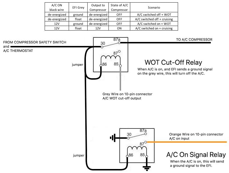
Holley Hyperspark Full Size Jeep Network. Holley Efi 550 937f Terminator X Fox Body Mustang 5 0 Kit. Here S My Holley Terminator Max A C Wiring Diagram Third Generation F Body Message Boards. Sniper efi a c control wires 4150 550 510 shiny 511 wiring the holley infinitybox fuel injection and question hot system for nitrous oxide 4 injector ...
Holley Hp Efi Wiring Diagram from www.efisystempro.com Effectively read a cabling diagram, one provides to find out how the components in the system operate. For instance , when a module is usually powered up and it also sends out a new signal of fifty percent the voltage in addition to the technician does not know this, he would think he ...
WIRING MANUAL & DIAGRAMS 199R10555 HP EFI and Dominator EFI Systems ... Holley offers a USB cable with a sealed connector, PN 558-409 for applications were the USB cable will be plugged in, and the ECU is mounted in a dirty environment. HP ECU - The HP ECU has two main connectors:
HP/Holley Dual Sync/MSD 6AL-2 Combo Wiring Diagram? On my 'scratch-build' (no OEM stuff) E85 powered, N/A big block Ford street rod with the Holley HP ECU (554-113), I'm using the Holley 558-508 main harness, Holley 565-210 Dual Sync distributor, and sensor numbers 554-101, 534-20, 534-10, 554-102, 554-103. Also using MSD 6421 6AL-2 & MSD 8253 ...

Wiring Manual Diagrams 199r10555 Wiring Manual Diagrams 199r10555 Hp Efi And Dominator Efi Ecu Pdf Document

Holley Efi Can Tachometer Image Tohatsu Tldi Tachometer Wiring Diagram Gauge Disk Clock Tower Architecture Transparent Png Pngset Com







0 Response to "37 holley hp efi wiring diagram"
Post a Comment