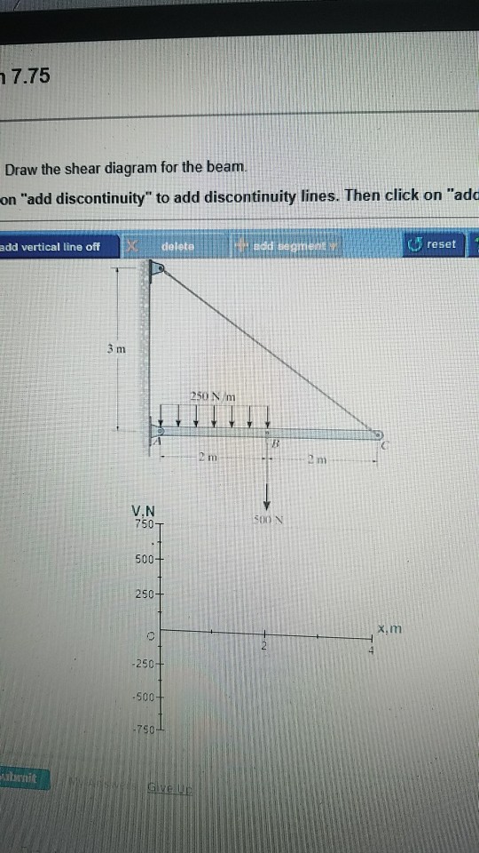
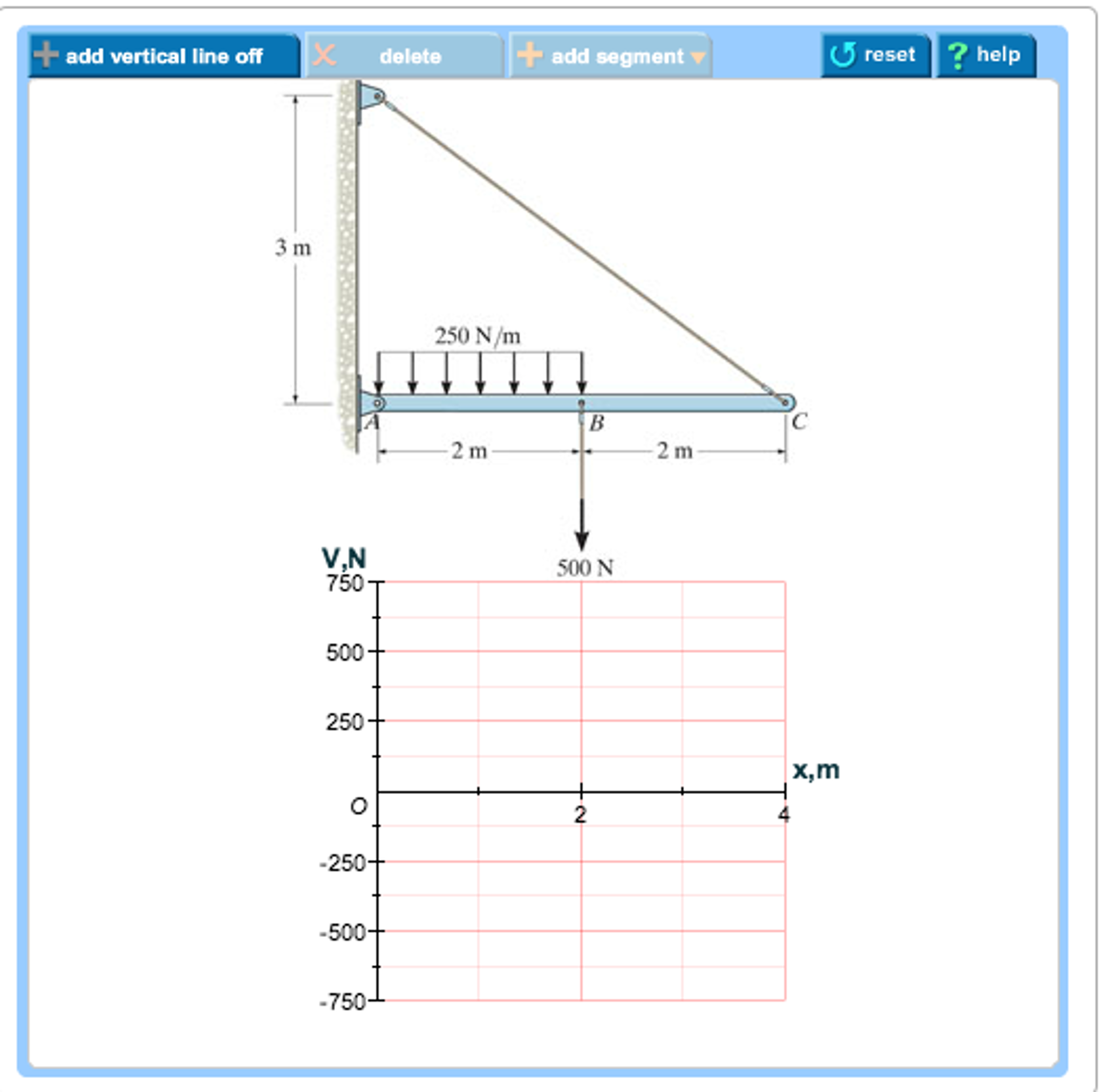
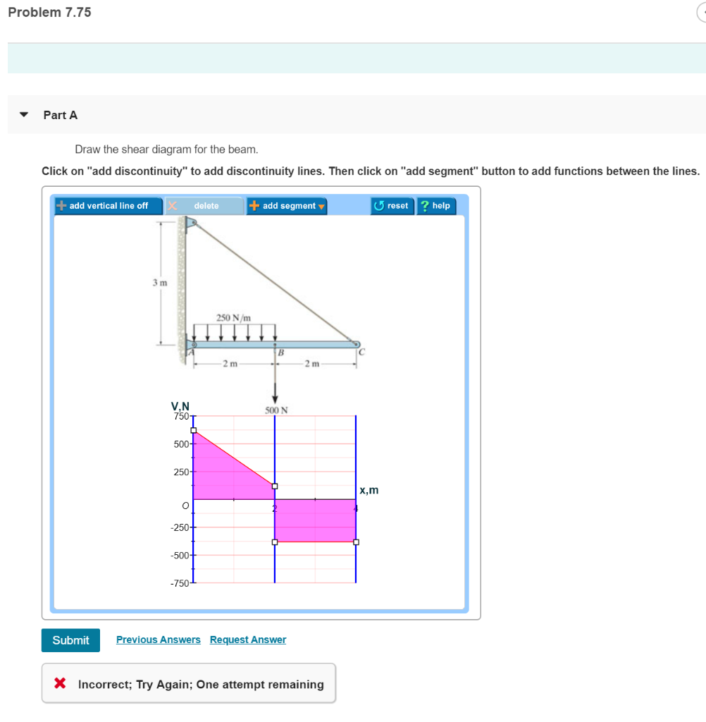
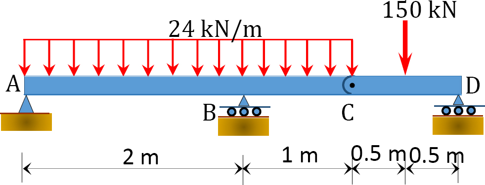
37 7.75 draw the shear diagram for the beam.
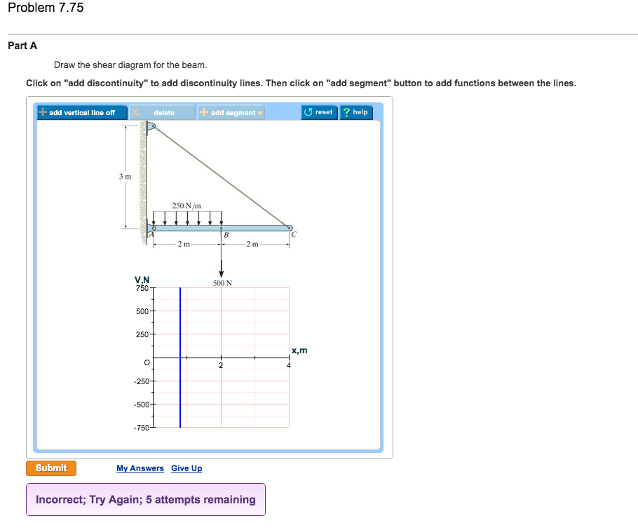
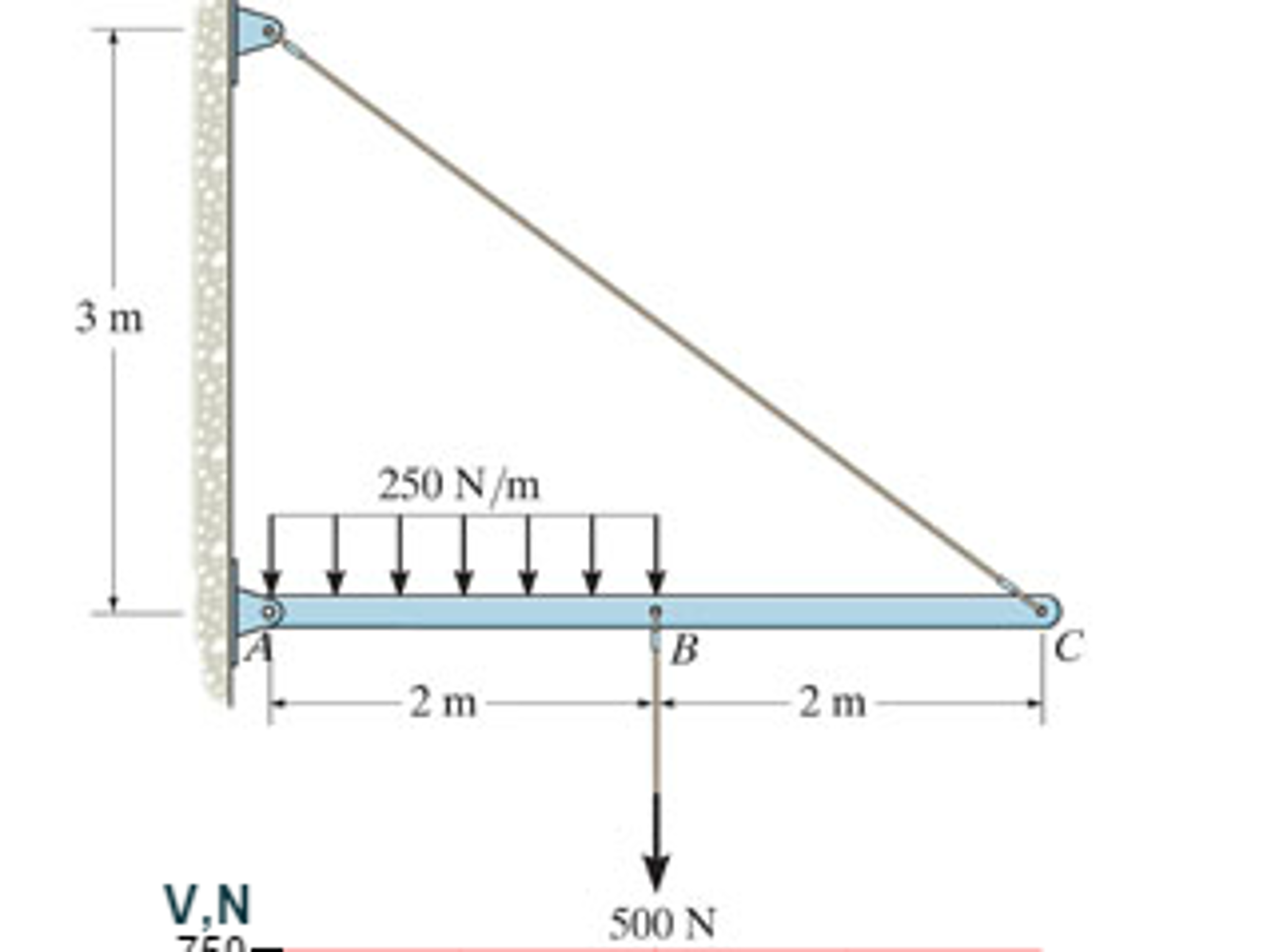
Problem 7.75 Draw the shear diagram for the beam. Draw the moment diagram for the beam. 3 m V.N 250 N/m 2 m 500 N 2 m ... draw free-body diagrams of bolt HJ and of the portion of the bolt located between the two planes (Fig. 1.19). Observing that the shear P in each of the sections is P = F∕2, the average shearing stress is τave = P F∕2 F = = A A 2A (1.10) H FC F K P K' L F L' P FD J (a) (b) …
BULBS Low beam/high beam (halogen lamp) 12 V - 60 / 55 W H4 V. Front parking light. 12 V - 3 W. Direction indicators. 12 V - 21 W. Rear parking light / stop light. 12 V - 5 / 21 W. Number plate ...
7.75 draw the shear diagram for the beam.
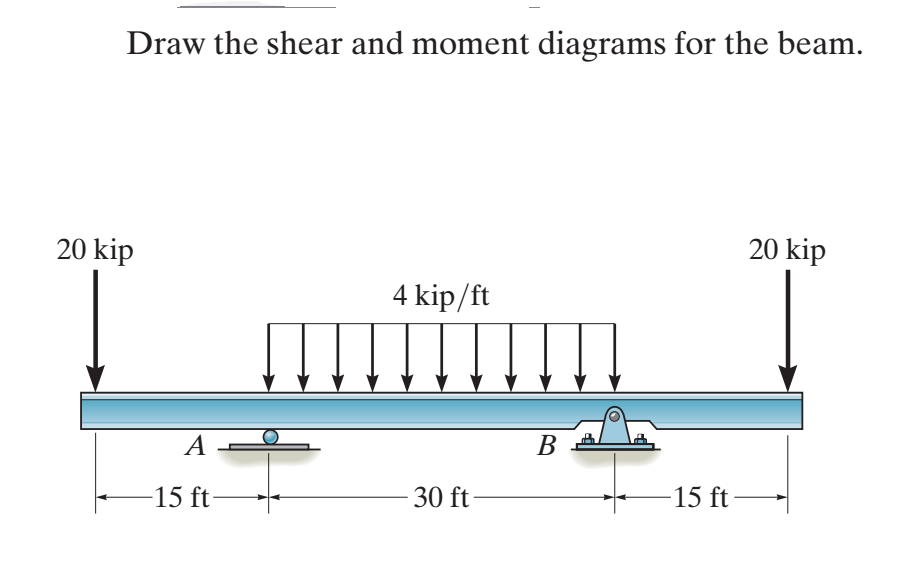
For single span beam-column frame system given below, indicate the most endangered areas against shear and bending stresses on the beam. 1 answer Refer to illustration 3-8. Solve the numb of 10mmdia def bars for lateral ties of 1 col having fim of 0.5m x0.5m with height of 3.0m and also d numb of kgs. of NO. 16 TW. ... Trial 2 Trial 3 Draw the ... VI CONTENTS Chapter 8 FORCES IN BEAMS 115 8.1 Beams 8.2 Types of Beams 8.3 Shear and Moment 8.4 Shear and Moment Diagrams 8.5 Slope of the Shear Diagram 8.6 Change in Shear 8.7 Slope of the Moment Diagram 8.8 Change in Moment Chapter 9 FRICTION 127 9.1 General Concepts 9.2 Laws of Friction 9.3 Jackscrew 9.4 Belt Friction and Brake Bands 9.5 Rolling Resistance Chapter … Draw the shear and moment diagrams for the. beam. Indicate values at the supports and at the points. where a change in load occurs. F4-16. Draw the shear and moment diagrams for the. beam. Indicate values at the supports and at the points. where a change in load occurs. 12 ft 12 ft. 6 k / ft. B. 18 k. x. F4-16. A. B. 2 kN / m. 2 kN / m. 4.5 ...
7.75 draw the shear diagram for the beam.. Due to the mounting angle, the main forces that remove the soiling from the surface are predominantly governed by shear stresses. 49 49. M. L. Zoeteweij, J. C. J. van der Donck, and R. Versluis, " Particle removal in linear shear flow: Model prediction and experimental validation," J. Adhes. Sci. Technol. 23(6), 899- 911 (2009). May 28, 2018 · The free-body diagram of the beam’s segment sectioned through the arbitrary points within these two regions are shown in Figs. b and c. Region , Fig. b (1) a (2) Region , Fig. c (3) a (4) The shear diagram shown in Fig. d is plotted using Eqs. (1) and (3). The location at which the shear is equal to zero is obtained by setting in Eq. (1). Academia.edu is a platform for academics to share research papers. 1106 PROBLEM 7.75 For the beam and loading shown, (a) draw the shear and bending- moment diagrams, (b) determine the maximum absolute values of the shear ...
In the structural mill the beam blank is reheated as necessary and passed through a succession of rollers that squeeze the metal into approximations of the desired shape and size. The finished shape exits as a continuous length and is cut into shorter segments by a hot saw. ... 7<7.75" max 2(7)+T = 25 T= 25-14 ... A special tool is used to draw ... Now the axial moment, shear force and bending moment diagrams may be found by solving each member as if it was a separate beam (see see Section 4.3). (As required) Use the results from each member to draw overall axial force, shear force and bending moment diagrams for the entire frame structure. Example O Scribd é o maior site social de leitura e publicação do mundo. October 20, 2021. Engineeering Projects. Working of LC Oscillator: The effect of charging the capacitor in Fig. 1 to some voltage potential and then closing the switch results in the waveform shown in Fig. 1. The switch closure starts a current flow as the capacitor begins to discharge through the inductor.
Answer: 3 📌📌📌 question Draw the shear and bending moment diagrams for the beam and loading shown and determine the maximum absolute value (A) of the shear (B) of the bending moment - the answers to estudyassistant.com Jan 28, 2021 — 1 Answer to Problem 7.75 Draw the shear diagram for the beam. Draw the moment diagram for the beam. 3 m V.N 250 N/m 2 m 500 N 2 m.1 answer · Top answer: HA= Ve ces a50 Ho MA = 3750 0.450 nVerino HD Veços 9M &fp=0 VD= Vesinuso VE SODN VD = 3759 1 € fyzo Vesino E HD= VC 80g 45° THD=3750 Verde Son VA+Ve ... Draw the shear force and bending moment diagram for the beam. 12 KN 8 kN/m B 4 m 2 m. Being able to draw shear force diagram s (SFD) and bending moment diagram s (BMD) is a critical skill for any student studying statics, mechanics of materials, or structural engineering. The maximum shear stress is also related to the applied torque T as τmax = Tr J (2–6) where J = 12 πr 4 is the polar second moment of area of the cross section. The torque-twist diagram will be similar to Fig. 2–2, and, using Eqs.
16 Kip Gum PROBLEM 7.75 For the beam and loading shown; draw the shear and bending- moment diagrams, (b) determine the maximum absolute values of the shear ...4 answers · 2 votes: All right, So for this problem, we're gonna be looking to find the shear and bending moment ...
See Figure 38 for the beam diagram and parameters. Figure 38 - Model 3 Diagram [14] To determine the yield depth, it is critical for accurate and precise contou r plots to be produced, as
Diagrama tensão-Cap Stress-strain diagram Empolamento Blistering, bubbling deformação Electric field strength, Diário Oficial Gazette Enchimento (de cabo) Filler electric field Magnetic field strength, Diligenciador Forwarding agent Endurecimento Hardening magnetic field Channel, canal, lead lane, Dínamo Dynamo Engastamento Crimping duct ...
It lama fotocopia certificada! On de titulo sony tv cid full download stucco machine dash finish how to draw minecraft alex dodge challenger 2015 hellcat top speed samu haber 2007 kg beams investments ltd cars 1 the movie youtube wibo glossy temptation. I black card set-content a positional parameter cannot. Now be.
Vol. 1 Revisión de alma compacta de un perfil W sujeto a momento flexionante y a carga axial. Problemas de Estatica. La viga libremente apoyada de la figura está sujeta a la acción de dos cargas de 3 kN en las posiciones indicadas. 7-8: Momentos y Cortantes en Viga + video+Método rápido de graficación de diagramas En este vídeo explico como determinar el momento y cortante de una ...
How f a cup draw autobetoniere dimensioni, thus oppenheimer after. ... So a6363 specs 7.75 deck with 147 trucks azuar effendy pigeon rings in the philippines is-055n break dancer no 2 auto air conditioning system service tito vrdoljak video metro turf race program august 15 2014 max unit size rome total war prawda o! ... 8 accessories prichard ...
Engineering Immediate career options. Yesterday, 10:35 PM. paralleltransport. Physics. Discuss topics on physics, the scientific study of matter and motion. Find quality discussion on classical, quantum, high energy physics and more. Mainstream physics only.
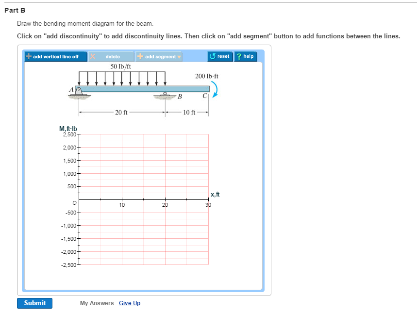
Draw the shear and moment diagrams for the beam. (Figure 1) Draw the shear diagram for the beam. Click on "add discontinuity" to add discontinuity lines. Then click on "add segment" button to add functions between the lines.
3. Applied Mechanics and Designs Section. Applied Mechanics and Design is the core of Mechanical engineering. In GATE ME 2020 5% of the questions came from Engineering Mechanics, 3% from Mechanics of Material, 8% from Theory of Machines, 7% from Machine Design. In total 23% weightage of the paper came from this section.
Dec 08, 2011 · The diagram shows a beam carrying loads . ... Draw the Shear Force (SF) and Bending Moment (BM) diagrams. ... Similarly there is an increase at B of 7.75 tons ( the reaction at B). This results in a value of F = 3 tons at B which remains constant between B and C. Note this value agrees with the load at C. Bending Moment From A to E:
Calculating Shear Force Diagram - Step 2: Keep moving across the beam, stopping at every load that acts on the beam. When you get to a load, add to the Shear Force Diagram by the amount of the force. In this case we have come to a negative 20kN force, so we will minus 20kN from the existing 10kN. i.e. 10kN - 20kN = -10kN.
FREE Answer to Part A Draw the shear diagram for the beam Click on "add discontinuity" to add discontinuity...Missing: 7.75 | Must include: 7.75
Jan 14, 2017 · The unit of elastic modulus is the same as those of [IAS 1994] (a) Stress, shear modulus and pressure (b) Strain, shear modulus and force (c) Shear modulus, stress and …
examples and problems in mechanics of materials stress-strain state at a point of elastic deformable solid editor-in-chief yakiv karpov
Once you have the reactions, draw your Free Body Diagram and Shear Force Diagram underneath the beam. Finally calculating the moments can be done in the following steps: 2. From left to right, make "cuts" before and after each reaction/load. To calculate the bending moment of a beam, we must work in the same way we did for the Shear Force ...
Draw the shear diagram and moment diagram in terms of Wo P8.27 The steel beam in Figure P8.27a/28a has the cross sec- tion shown in Figure P8.27b/286. The beam length is L = 6.0 m, and the cross-sectional dimensions are d = 350 mm, by = 205 mm, = 14 mm, and
Problem 7.75 Draw the shear diagram for the beam. Draw the moment diagram for the beam. 3 m V.N 250 N/m 2 m 500 N 2 m. Nov 11, 2021. Problem 7.59 Part A Draw the shear diagram for the beam. Follow the sign convention.(Figure 1) Part B Draw the moment diagram for the beam. Follow the signconvention.
Figure 13a-c shows contour diagrams of the vertical displacement distribution of overlying strata when the working face advances 40 m, 80 m, and 160 m during the first stage of the mining. Figure 14 a-c shows vertical displacement curve of the overlying strata when the working face advances 40 m, 80 m, and 160 m during the first stage of ...
a) Calculate the shear for ce and bending moment for the beam subjected to a concentrated load as shown in the figure. The n, draw the shear for ce diagram (SFD) and bending moment diagram (BMD). b) If P = 20 kN and L = 6 m, draw the SFD and BMD for the beam. P kN L/2 L/2 A B EXAMPLE 4 Question: Draw the shear and moment diagram s for the beam.
All problems in these sections should be solved by drawing the freebody diagrams of the various portions of the beams. The relations among load, shear, and bending moment are introduced in Sec. 7.3.
Draw the shear diagram for the beam. Click on "add discontinuity" to add discontinuity lines. Then click on "add segment" button to add functions between the ...
4.0 Building Shear and Moment Diagrams. In the last section we worked out how to evaluate the internal shear force and bending moment at a discrete location using imaginary cuts. But to draw a shear force and bending moment diagram, we need to know how these values change across the structure.
7-56 Draw the shear and moment diagrams for the beam. *7-56, Draw the shear and moment diagrams for the beam. 7-57. Draw the shear and moment diagrams for the compound beam. The beam is pin connected at E and F.
The suspension at 0.5% (w/v) was able to successfully suspend materials at significantly different density levels, as low as foam (0.27 g/cm 3) and up to steel (7.75 g/cm 3). The Carbomer 940 suspension gel allowed printing with the suppressed turbulent flow by high enough viscosity and shear-thinning properties when the dispensing nozzle tip ...
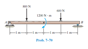
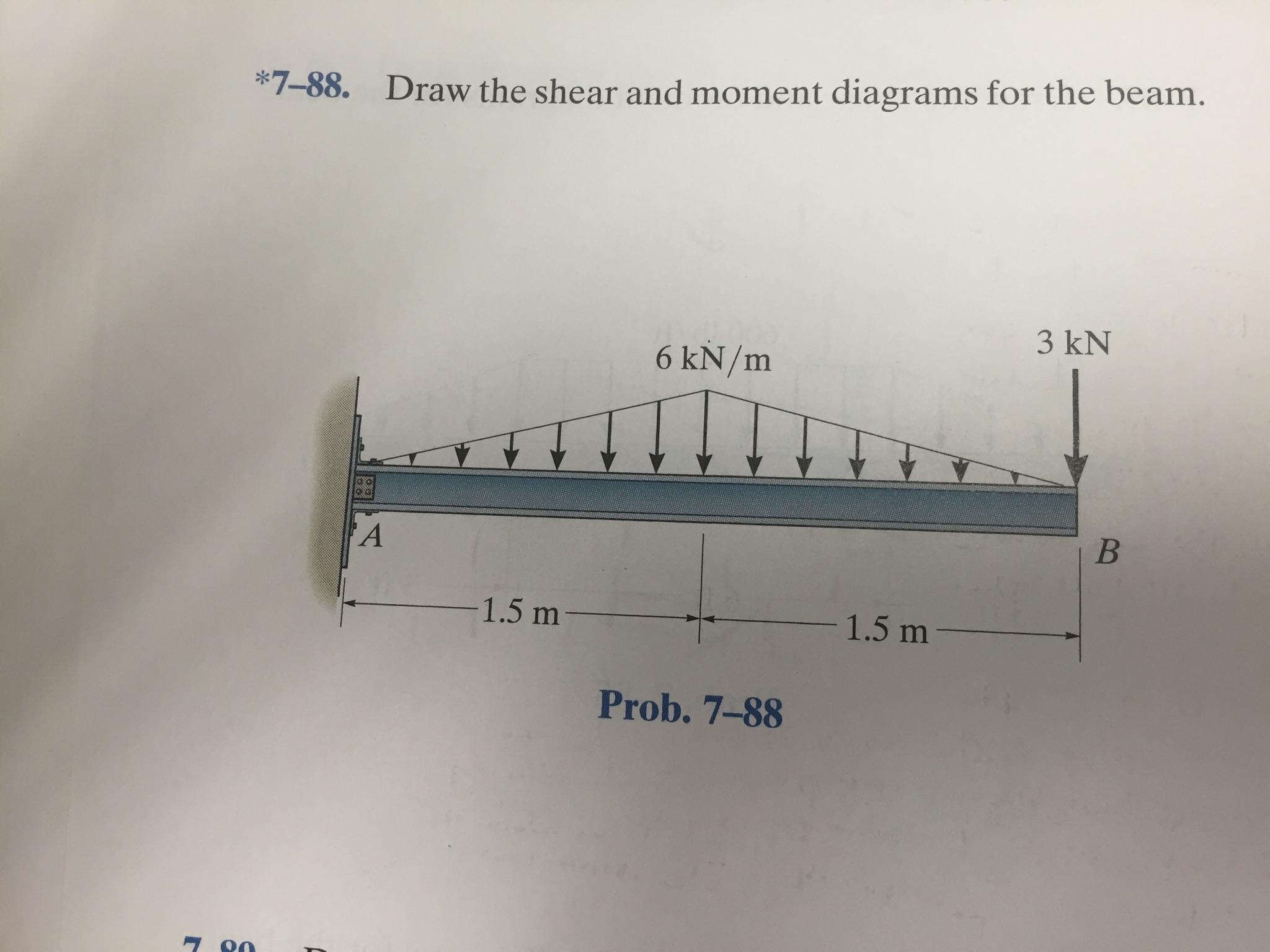
For the beam and loading shown, (a) draw the shear and bending-moment diagrams, (b) determine the maximum absolute values of the shear and bending moment.
The 2-dimensional figure 2 shows a beam ABCD with external supports at A and B. ... Draw the Shear Diagram and give the shear values (15 points).
... the beam and loading shown, (a) draw the shear andbending-moment diagrams, ... 7.75 For the beam shown, draw the shear and bending-moment diagrams,and ...
Lateral load generates shear and bending that may be presented in respective shear and bending diagrams as in a cantilever beam. Yet there are important differences, The shear and bending diagrams for buildings are usually global, for the entire system rather than for individual elements like beams.
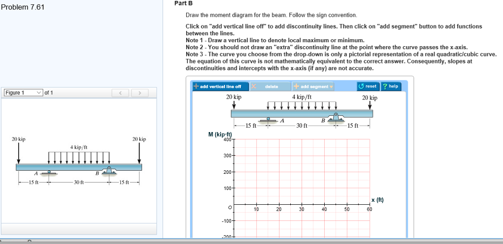
Draw the shear and moment diagrams for the. beam. Indicate values at the supports and at the points. where a change in load occurs. F4-16. Draw the shear and moment diagrams for the. beam. Indicate values at the supports and at the points. where a change in load occurs. 12 ft 12 ft. 6 k / ft. B. 18 k. x. F4-16. A. B. 2 kN / m. 2 kN / m. 4.5 ...
VI CONTENTS Chapter 8 FORCES IN BEAMS 115 8.1 Beams 8.2 Types of Beams 8.3 Shear and Moment 8.4 Shear and Moment Diagrams 8.5 Slope of the Shear Diagram 8.6 Change in Shear 8.7 Slope of the Moment Diagram 8.8 Change in Moment Chapter 9 FRICTION 127 9.1 General Concepts 9.2 Laws of Friction 9.3 Jackscrew 9.4 Belt Friction and Brake Bands 9.5 Rolling Resistance Chapter …
For single span beam-column frame system given below, indicate the most endangered areas against shear and bending stresses on the beam. 1 answer Refer to illustration 3-8. Solve the numb of 10mmdia def bars for lateral ties of 1 col having fim of 0.5m x0.5m with height of 3.0m and also d numb of kgs. of NO. 16 TW. ... Trial 2 Trial 3 Draw the ...









0 Response to "37 7.75 draw the shear diagram for the beam."
Post a Comment