37 700r4 valve body diagram
Sonnax valve body layouts provide a detailed overview of individual units making it quick and easy to determine what's available for the specific valve body you're working on. Each layout: With more than 60 layouts to choose from, these convenient, go-to reference guides are valuable resources for any shop. View, download or print these ... Lockup TCC Wiring from 700r4 transmission wiring schematic , source:rowand.net 9258 700r4 Converter Lock Up Wiring Kit Diagram from 700r4 transmission wiring schematic , source:brianna-mr0903.changeip.com 4r70w Valve Body Diagram E3 wiring diagram from 700r4 transmission wiring schematic , source:11.b3.latex-kissen.de
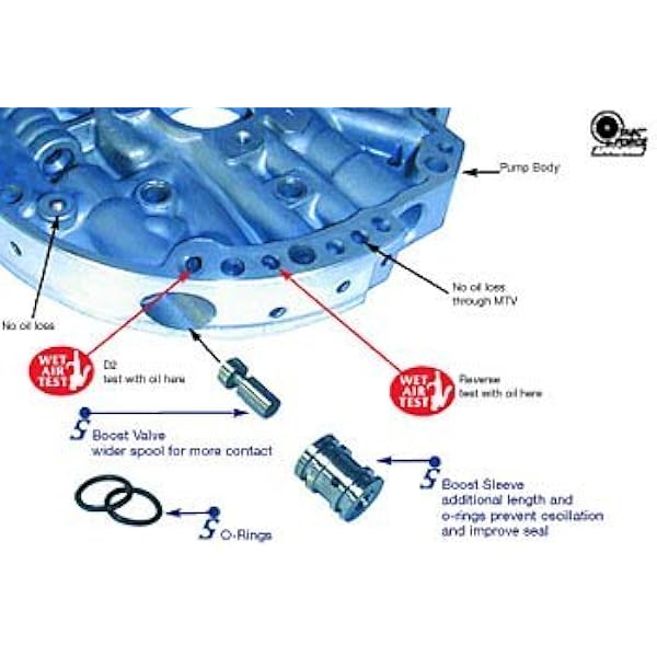
Beginning on June 28, (Julian Date 180) 1984, all THM 700-R4 transmissions were built with a new Pump Body and Pump Cover Assembly with an added oil dam in both components, as shown in Figure 10. To reduce oil pump fluid leaks. OIL PUMP BODY - Oil dam added to the pump body casting in the line pressure passage, as
700r4 valve body diagram
A 700R4 usually has 3 switches on the back of the valve body.the one closest to the 1-2 accumulator (pass. side rear corner) is the fourth switch. If you have a two piece case, you have a 4L60E,the pressure switch is still on the valve body but it is an assembly,not a single switch. valve body. (See Photo 4A.) Some 700R4 transmission do not have this auxiliary valve body but came with a small support plate. If you have this type of 700R4 transmission, remove the four bolts holding the small support plate to the case at the rear of the valve body. Remove the two valve body bolts holding the throttle pressure mechanism. 78 General Motors 2008 AUTOMATIC TRANSMISSION KIT & COMPONENTS CATALOG ©2008 PARKER HANNIFIN CORP. ALL RIGHTS RESERVED *Prefix Letter 'T' denotes Toledo-Trans Kit (TTK) Brand Transmission Kits
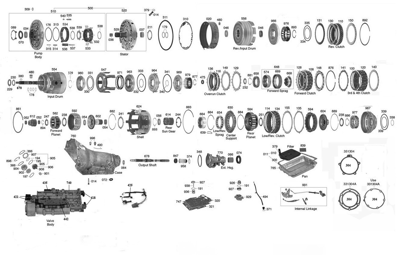
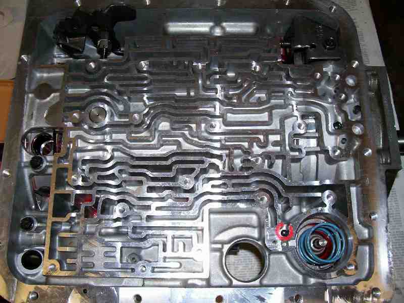
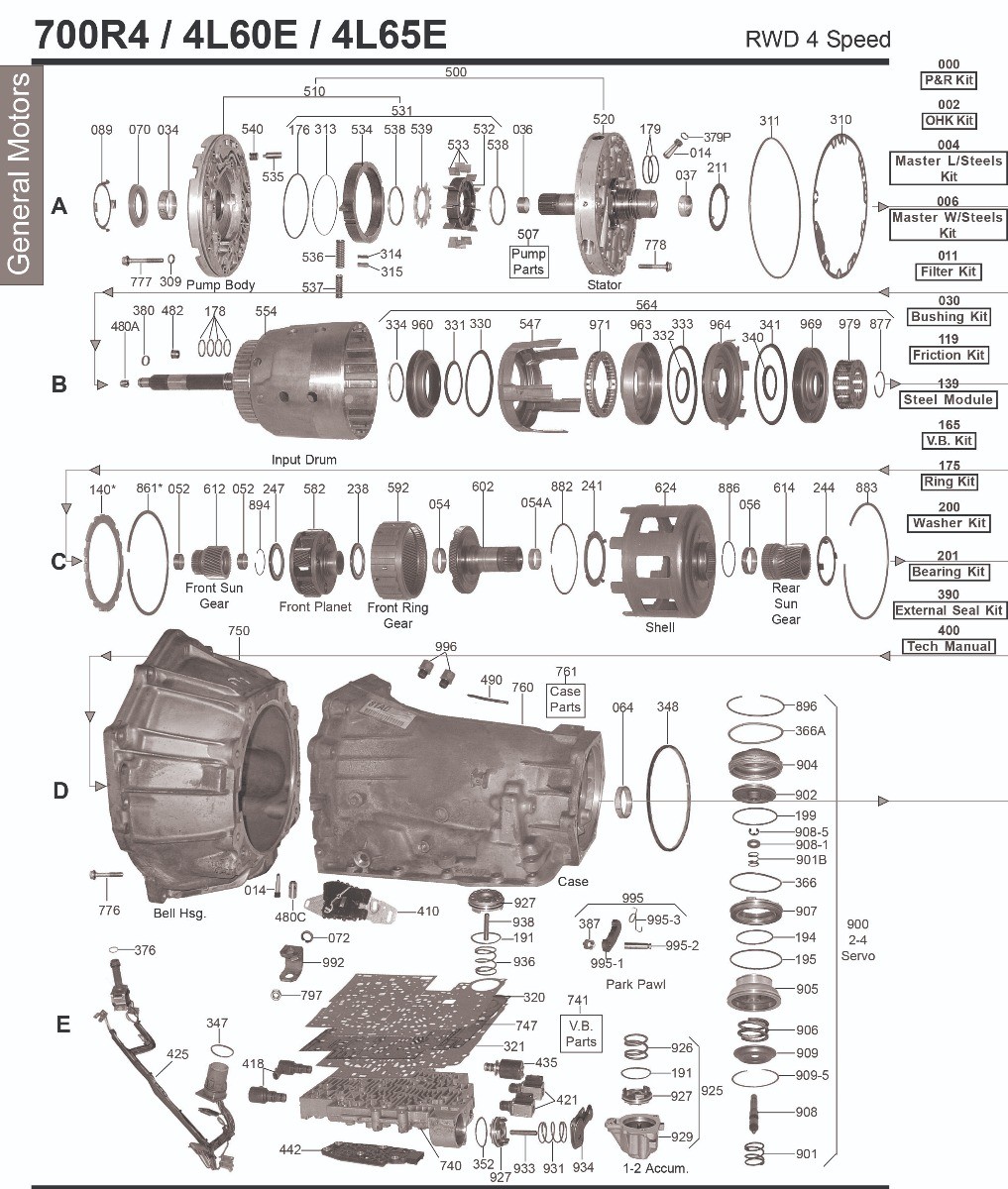
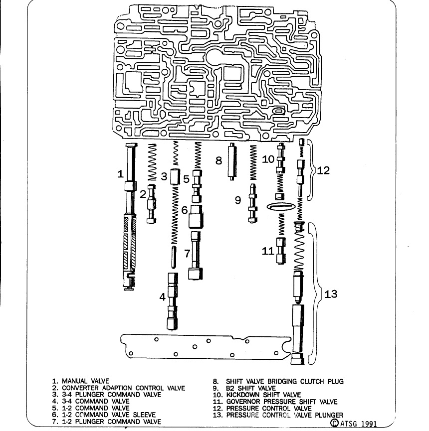
700r4 valve body diagram. 700R4 transmission diagrams needed. I am facing the task of removing the valve body on the 700R4 in my 1992 Chevy G20 van, due to it still not wanting to up shift from low. what I am wanting to find, is an exploded view of the valve body assembly,and any diagrams showing where any check balls may be located. Posted by Jeff Wecker on Jul 31, 2009. 700 Pump & Reverse Drum 700R4 Case & Components 700R4 Planets & Shell 700R4 VB & Pan 700R4-Drum-Components. 2004r. Directs and Forwards Case and Valve Body. 4L60E. Input Drum Pump and Reverse Drum Valve Body and Pan Case and Components. 4L80E. Planets Forward Direct Drum Case and Valve Body Stator ... Temp Gauge Wiring Diagram. Tuned Port ... TeckPak Bushings, Electrical Parts and Modulators. Transel Tech Manuals. TransGo Valve Body Kits. TransTec Overhaul Kits. 700R4 Parts. 700R4 (Parts Not Pictured , kits, manuals, etc) Click on a section to see a detailed view. Click on a part number to view part variations, pricing, and availability. The valve body consists of precision fit compo-nents which will not tolerate dirt or burrs. STEP 8. Heavy Duty and Street; MTV upshift valve (See Fig. 5.) Remove the pin at the end of the MTV upshift valve bore. Remove the plug, valve and spring from the bore. Set the spring aside (it will not be re-used.) Re-install the valve, plug and pin in ...
the valve body. In most 1986 and later TH-700's the TCC shift valve was plugged and TCC is controlled by an Elec-tronic Control Module (ECM). ALL B&M TH-700 (4L60) TRANSMISSIONS ARE BUIL T FOR ECM CONTROL OF THE TCC. If you are replacing a 1982-87 transmission with hydraulic TCC control you will have to do one of the Part 20-95 and 20-121. 4L60E Valve Body 2001-2002 (rebuilt, updated and tested. 4l60e 65e 70e technical thread, cooler install codes. 6 Best Images of 700R4 Exploded Diagram - 4L60E. 700r4 Valve Body Exploded View Diagram - Wiring Diagram. Diagram 4l60e Transmission Pictures, Images & Photos. 700r4 chevrolet automatic transmission valve body identificationI strive to find the best deals on the quality products we use. To save you and I time and m... the valve body casting. Finding them first in an oil circuit diagram makes them even easier to locate in the valve body and separator plate. Keep in mind that some of these holes are located in one of the casting walls, while others are in the valve itself. 5R55N - Fighting a 2-3 Flare Hi, I'm John from Springfield, Missouri.
FTI Performance 700R4-3H - FTI Performance 700R4 Level 3 Transmissions. Automatic Transmission, 4-Speed, Level 3 with Holley TV Cable, Forward Shift Pattern, Automatic Valve Body, GM, 4L60/700R4, Each. Part Number: FTI-700R4-3H. ( 2 ) Estimated Ship Date: Monday 11/8/2021. Core Charge $200.00. Freight Charge. Estimated Ship Date: Monday 11/8/2021. 700R4 Remanufactured Valve Bodies. 1982 - 87, With TCC Bore Part No. 20-116. 1987 - 92, W/ Aux Valve Body, With TCC Bore Part No. 20-117. I need a valve body diagram for a 1990 corvette 700r4. I need a diagram showing all the valves and springs, their - Answered by a verified Chevy Mechanic We use cookies to give you the best possible experience on our website. 87 was a changeover year on the 700r4. the early 87 doesnt have the aux. valve body, and the late 87-up does. as far as i know, you cant swap them. maybe crosley will see this and chime in. he knows more about these trans on these kinds of details than i do. K.
Trans Parts Online 700 4l60e Transmission Parts
SHIFT KIT® Jr. Valve Body Repair Kit Fits 1988-93 700R4, 4L60 700-2&3. Reprogramming Kit™ ...
4l60e Disassembly
sions now have this auxiliary valve body (See Photo 4A.) Some 700R4 transmissions do not have this auxiliary valve body but came with a small support plate. If you have this type of 700R4 transmission, remove the four bolts holding the small support plate to the case at the rear of the valve body. Remove the two valve body bolts holding the

700r4 Has A Shutter In Od The 1947 Present Chevrolet Gmc Truck Message Board Network
4L60E Valve Body Rebuild Instructions; 4L60E/4L65E Rebuild Kit Options; GM 4L60E Hardware Torque Specifcations; 4L60E Filter Style Guide; 4L80E Hardware Torque Specifications; Marine Transmission Information . Velvet Drive 71C/72C Torque Specs
700r4 Accumulator Pistons Hot Rod Forum
Registered. Joined Dec 15, 2007. ·. 6,009 Posts. #4 · Aug 15, 2008. Haven't done a 700R4 but the 2004R is 9 - 12 ft. lbs. or 100-120 inch. lbs. The valve body can also be torqued like a head bolt pattern.
Atra Com
In summary, the 700r4 transmission was a 4-geared hydraulic automatic transmission with the 4th gear, an overdrive gear (30% increase). The transmission was made between 1982-1992. It had a case length of 23.5″~ and a weight of 170 lbs~ without fluid inside it.
700r4 4l60 4l60e 4l65e General Motors Automatic
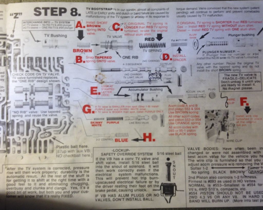
700R4 Valve body interchange GM June, 1992 STEP 1: Identify the year of the valve body. 82-87 valve bodies can be identified by 2 aluminum sleeves in the 1-2 shift valve line-up. All 1988 or later valve bodies have only one very long aluminum sleeve. Beginning in 1989 the converter clutch throttle valve bore was eliminated and a notch was ...

Sonnax 104740 23k End Plug Kit 6l80e 6l90e Includes 6 End Plugs 9 O Rings Patc Transmissioncenter Net
This is a video of a THM-700-R4 Transmission. It is very common that after you get done with one of this units, it will not want to upshift into 4th gear. My...

4l60e 4l65e Valve Body Pwm 96 03 Used Valve Body Tdu7474
valve body has been re moved. STEP 6: Remove the auxiliary valve body. Most 700R4 trans mis - sions now have this auxiliary valve body (Figure 2). During the removal of the aux il ia ry valve body, the check ball located inside will drop out. When re in stall ing valve body, this check ball must be used (Figure 3).

700r4 Auxiliary Valve Body Assembly 87 93
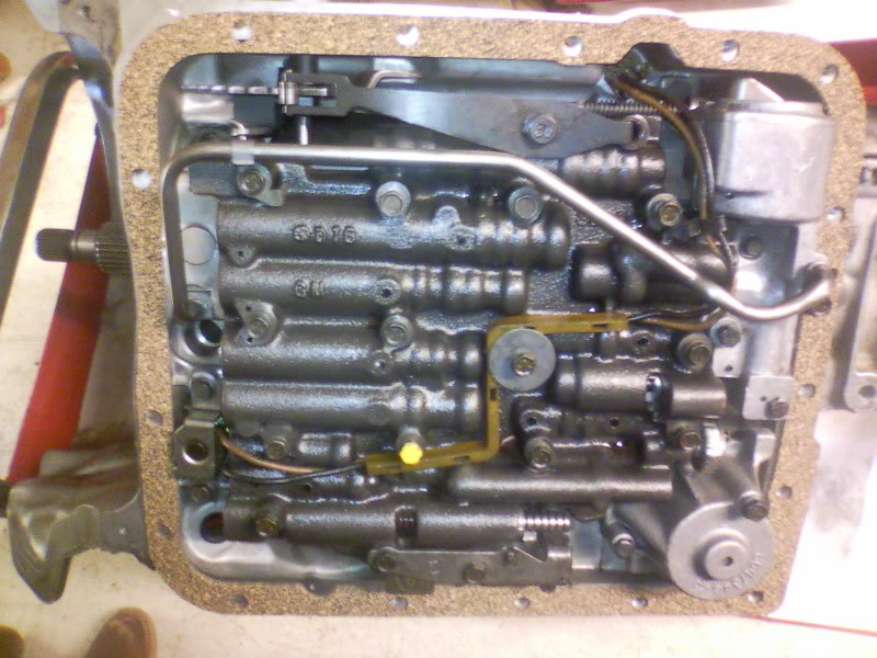
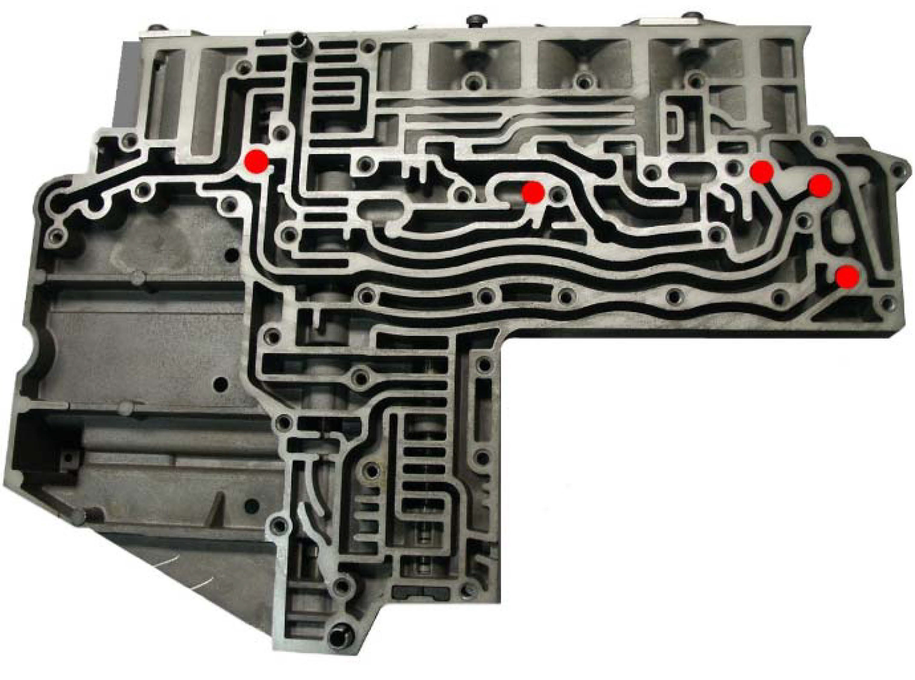
A604 Valve Body. valve body. Usually considered the brain of the transmission, most of the shifting valves of the transmission are located in it. 85 700r4 check ball locations in valve body. check ball locations for early model 700r4s every diagram i've seen doesn't my what i needed so i did it myself. 1985 700r4 valve body 001.
1
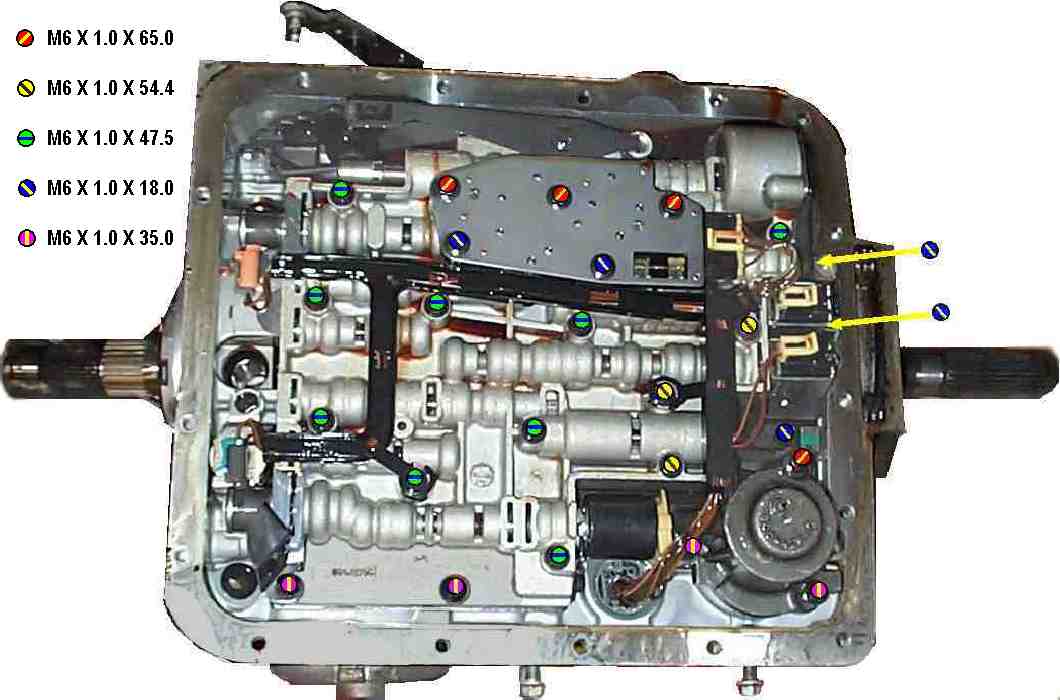
The kit does not give the torque sequence or torque spec on re-installing the valve body, kit didn't even come with seperator plate gaskets! If someone has a diagram on how to tighten the valve body down, I would be in great gratitude of getting a peek at it! Here is a pic to show you the sequence. Tighten them to 100 inch lbs.
700r4 Build Thread Page 9 The 1947 Present Chevrolet Gmc Truck Message Board Network
4l60e input drum pump and reverse drum valve body and pan case and components. 700r4 700 pump reverse drum 700r4 case components 700r4 planets shell 700r4 vb pan 700r4 drum components. You can also find other images like images wiring diagram images parts diagram images replacement parts images electrical diagram images repair manuals images ...

Toyota 35410 42050 Transmission Valve Body Assy Genuine Car Parts Rav4 J L Ebay
78 General Motors 2008 AUTOMATIC TRANSMISSION KIT & COMPONENTS CATALOG ©2008 PARKER HANNIFIN CORP. ALL RIGHTS RESERVED *Prefix Letter 'T' denotes Toledo-Trans Kit (TTK) Brand Transmission Kits
.jpg?v=1631565455473)
Sonnax Line Pressure Booster Kit 700r4 Lb1
valve body. (See Photo 4A.) Some 700R4 transmission do not have this auxiliary valve body but came with a small support plate. If you have this type of 700R4 transmission, remove the four bolts holding the small support plate to the case at the rear of the valve body. Remove the two valve body bolts holding the throttle pressure mechanism.
Documents Holley Com
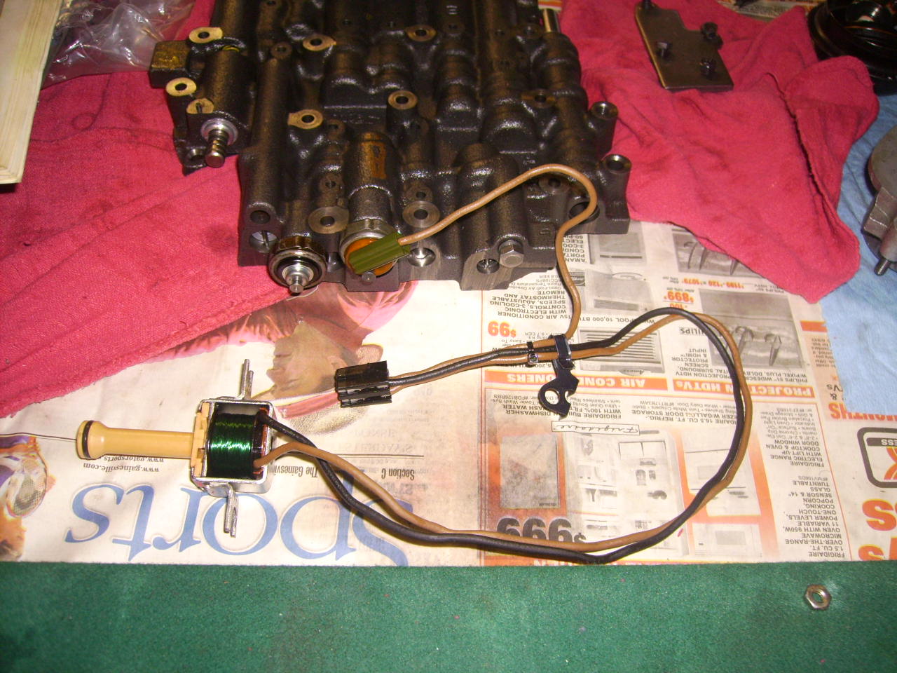
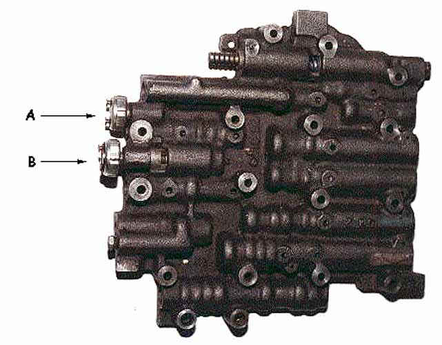
A 700R4 usually has 3 switches on the back of the valve body.the one closest to the 1-2 accumulator (pass. side rear corner) is the fourth switch. If you have a two piece case, you have a 4L60E,the pressure switch is still on the valve body but it is an assembly,not a single switch.

700r4 4l60 Experts Third Generation F Body Message Boards
Transmission Valve Body Components Rennlist Porsche Discussion Forums
Shinseiauto Com
700r4 Valve Body Wiring Question Corvetteforum Chevrolet Corvette Forum Discussion
700r4 Info Page 4

Tips For Your 700r4 Rebuild Shop Talk
Anyone Have A 88 700r4 Valvebody Installation Torque Sequence
Static Summitracing Com
1988 700r4 Transmission Pressure Switch Operation S 10 Forum

700r4 4l60 1987 1992 Non Auxiliary Valve Body Stock Remanuf

6r60 6r80 845re Zf8hp Zf6hp Hd Accumulator Piston Kit Global Transmission Parts

Sonnax Gm 4l80 E Case Checkball Locations

I Didn T See Wear 3 Of My 8 Check Came From When I Removed My 1990 700r4 Valve Body I Also Know I Do Not Need Them All
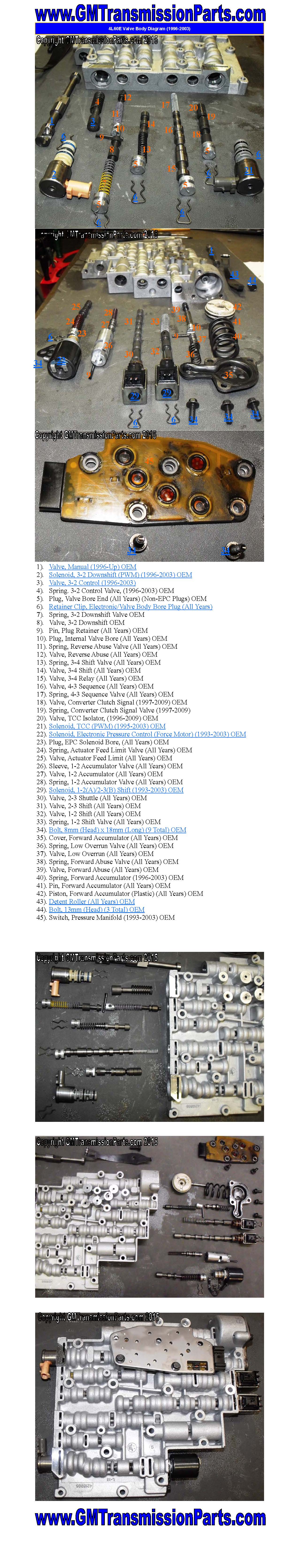
Gm 4l60e Transmission Valve Body Parts Diagram 1996 2003
Amazon Com Sonnax Reverse Boost Valve Sleeve 700r4 4l60 2004r Automotive
4l60e Assembly

Transgo 700r4 2 3 Reprogramming Kit High Performance Valve Body Shift Kit 1982 89 72 Picclick
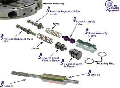
Sonnax Gm 700r4 Oversize Pressure Regulator Valve Automatic Transmission Oregon Performance Transmission

4l65e 700r4 4l60 4l60e Valve Body Premium Pwm On Off 96 E00 Sonnax Afl Tcc Acc Valves Epc Psi Manifold Other Sol T
Transmission Gurus 700r4 Tcc Solenoid With Harness Which One Third Generation F Body Message Boards
Sonnax 45rfe 545rfe 68rfe Checkball Locations
722 3 560sel Transmission Mercedes Benz Forum
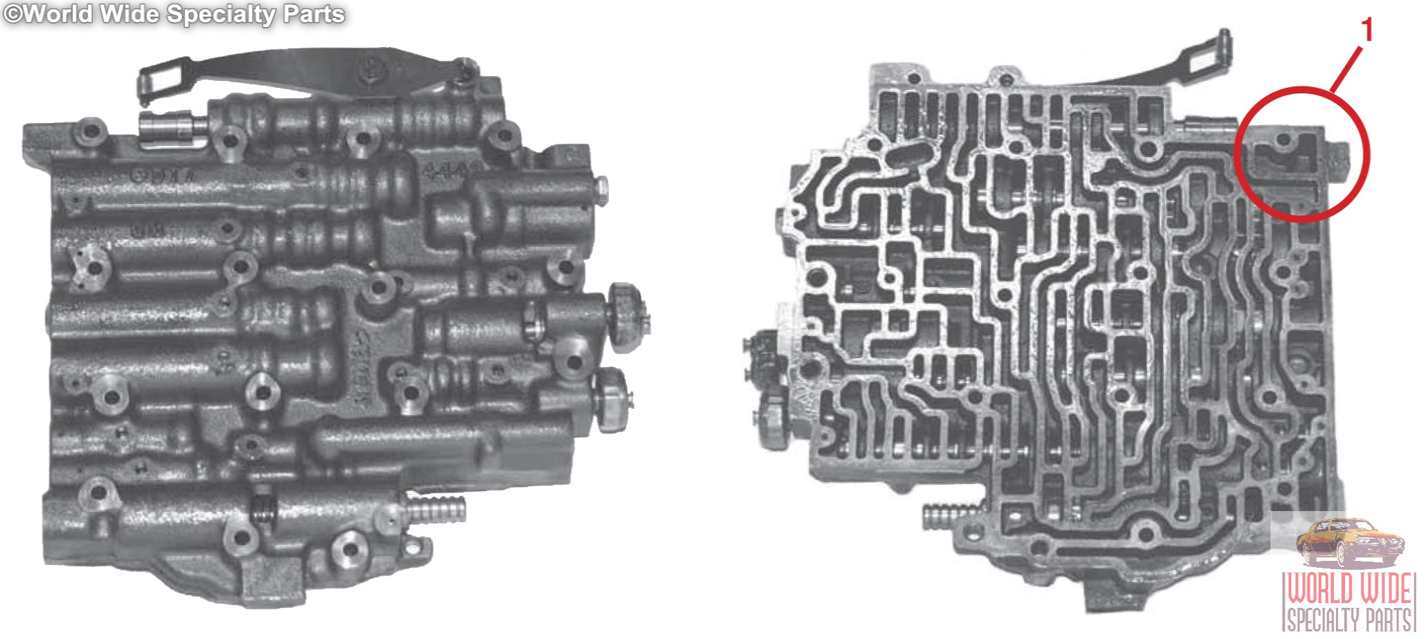
Gm 700r4 700 R4 Valve Body 1987 1992 Electronic Lockup World Wide Specialty Parts
0 Response to "37 700r4 valve body diagram"
Post a Comment