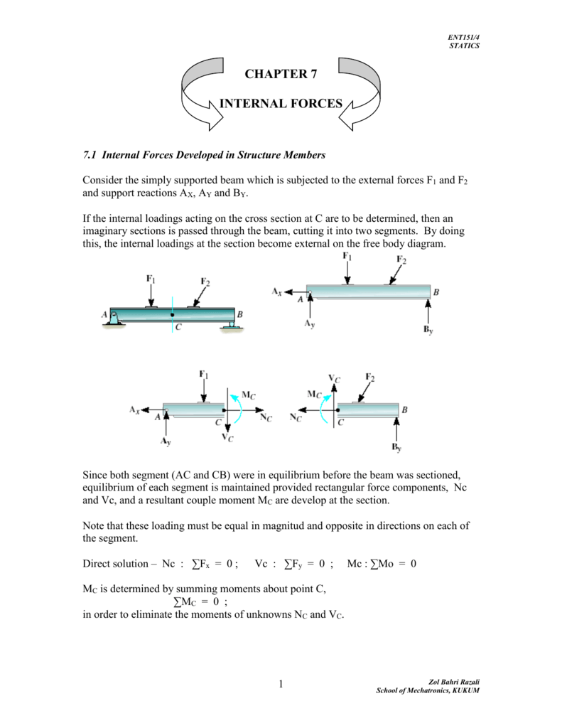
39 Two Force Member Free Body Diagram
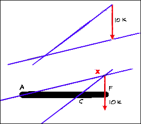
5.2: Two-Force Members - Engineering LibreTexts A two-force member is a body that has forces (and only forces, no moments) acting on it in only two locations. In order to have a two-force member in static equilibrium, the net force at each location must be equal, opposite, and collinear. This will result in all two-force members being in either tension or compression, as shown in the diagram ... Question about a simple free body diagram | Page 3 ... Feb 03, 2022 · The cord exerts a uniform radial force along a 90 degree arc of the ideal pulley's surface. The net of this is a force whose magnitude is ##\sqrt{2}## times tension at an angle 45 degrees below the horizontal. Of course, Newton's third law still applies. The cord is subject to a force from its two attachment points and from the pulley.
PDF FRAMES AND MACHINES - Purdue University a) Identify any two-force members in the frame. b) Draw the overall free body diagram and the individual free body diagrams of members ACE and BCD, and pulley E. c) Determine the forces at pin C on member BCD.
Two force member free body diagram
Free Body Diagrams, Tutorials with Examples and Explanations Example 8 : A system with two blocks, an inclined plane and a pulley. A) free body diagram for block m 1 (left of figure below) 1) The weight W1 exerted by the earth on the box. 2) The normal force N. 3) The force of friction Fk. 4) The tension force T exerted by the string on the block m1. B) free body diagram of block m 2 (right of figure below) Question about a simple free body diagram | Page 2 ... sysprog said: the second diagram is a free-body diagram; No, it's not. A free body diagram contains only one body, and it shows all the forces acting on that one body. To analyze a situation with more than one body, you draw a separate free body diagram for each body. there is no real apparatus involved -- it's an abstraction; PDF Equations of Equilibrium & Two- and Three-force Members TWO-FORCE MEMBERS & THREE FORCE-MEMBERS (Section 5.4) The solution to some equilibrium problems can be simplified if we recognize members that are subjected to forces at only two points (e.g., at points A and B). If we apply the equations of equilibrium to such a member, we can quickly determine that the resultant forces at A and B must
Two force member free body diagram. PDF 5 Solutions 44918 - TURMA 2014.2 - ENGENHARIA CIVIL Draw the free-body diagram of the winch, which consists of a drum of radius 4 in. It is pin-connected at its center C,and at its outer rim is a ratchet gear having a mean radius of 6 in. The pawl ABserves as a two-force member (short link) and prevents the drum from rotating. Explain the significance of each force on the diagram. (See Fig. 5-7b.) Determine the horizontal and vertical components force at ... Free Body Diagram:The solution for this problem will be simplified if one realizes that member [latex]BC[/latex] is a two force member. Equations of. Results. See All Results. Question: Structural Analysis [EXP-546] Determine the horizontal and vertical components force at pins A and C of the two-member frame. PDF Truss Analysis -Method of Joints - San Jose State University 1. Draw a Free Body Diagram (FBD) of the entire truss cut loose from its supports and find the support reactions using the equations of equilibrium (we will see that for some truss structures this step is not always necessary); 2. Draw a FBD of a truss joint that has no more than two unknowns and use the two equations of equilibrium to find the two unknown truss member forces; PDF Chapter 7 Trusses, Frames, and Machines 1. Draw a free-body diagram of the entire structure and determine the reactions (if r = 3). 2. Draw free-body diagrams for all members (assume tensile forces in all members) and all joints. 3. Set up the equilibrium equations for each joint and solve them one joint at a time, begin with those that have at most two unknowns. 4.
Free Body Diagram: Definition, Purpose, Examples, Steps ... All forces and moments acting on the object are represented using two dimensional or three-dimensional representation using the free body diagram or FBD concept. As the forces are vector quantity, FBD is also known as a vector diagram. In this article, we will explore more details about the free body diagram. Purpose of the Free Body Diagram Force - definition of force by The Free Dictionary force (fôrs) n. 1. The capacity to do work or cause physical change; energy, strength, or active power: the force of an explosion. 2. a. Power made operative against resistance; exertion: use force in driving a nail. b. The use of physical power or violence to compel or restrain: a confession obtained by force. 3. a. Intellectual power or vigor ... Free Body Diagram Questions and Answers - Study.com In each case, identify any two-force members, and then draw the free -body diagrams of each member of the frame. View Answer A collar B of weight W can move freely along the vertical rod. STATIC FORCE ANALYSIS - Middle East Technical University The free-body diagrams of the links in the four-bar mechanism are redrawn below. In this case to simplify the calculations we note that F ij = -F ji for the joint forces. Furthermore, since link 3 is a two-force member, F 23 and F 43 are equal, opposite and their line of action is along AB.
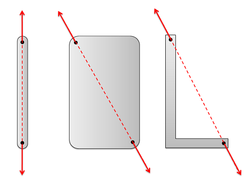
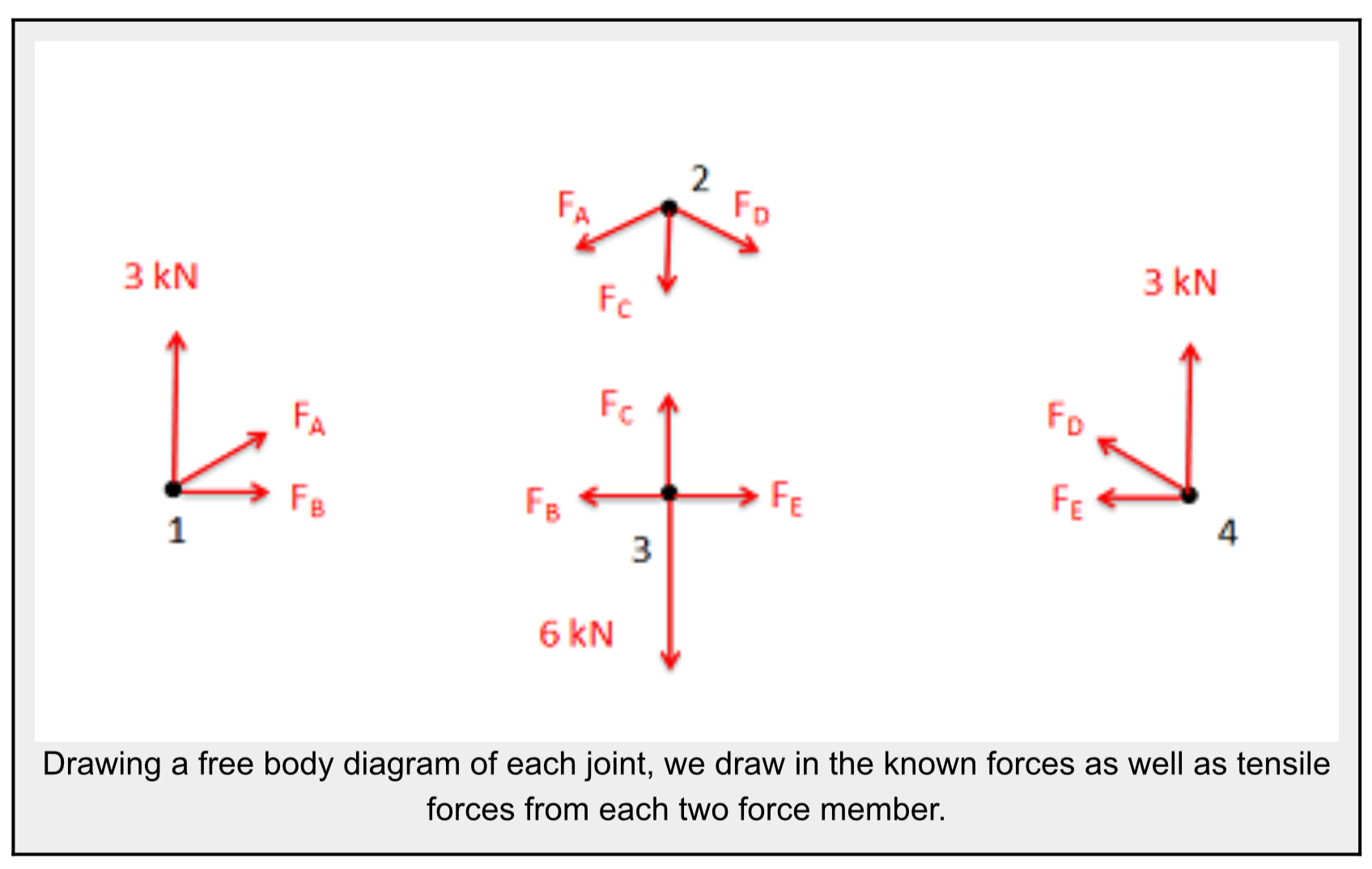
Structural Engineering: Free Body Diagrams - Top Dog Engineer The steps include: STEP 1: Identifying two force members. STEP 2: Drawing free body diagrams of each component. STEP 3: Solving for the external forces by applying equations of equilibrium. STEP 4: Flipping the direction of negative force vectors. If you want to learn from the ground up, please watch the video!! The analysis of trusses - University of Nebraska-Lincoln made of two force members all pin connected to each other. The method of joints: This method uses the free-body-diagram of joints in the structure to determine the forces in each member. For example, in the above structure we have 5 joints each having a free body diagram as follows Note how Newton's free body diagram worksheet-2 (1).pdf - Worksheet #1 Free ... Worksheet #1 Free Body or Force diagrams… Drawing Free-Body Diagrams Free-body diagrams are diagrams used to show the relative magnitude and direction of all forces acting upon an object in a given situation. A free-body diagram is a special example of the vector diagrams; these diagrams will be used throughout your study of physics. The size of the arrow in a free-body diagram is reflective ... What Is Zero Force Member for Truss | How to ... The free-body diagram of joint “C”, Fig – 2 (Truss Joint), indicates that the force in each member must be zero in order to maintain equilibrium. Truss Joint – Fig – 3. Furthermore, as in the case of joint “A” , Fig – 3 (Truss Joint) this must be true regardless of the angle say θ. between the members .
ME 141 Engineering Mechanics Portion 4 Analysis of Structure ...
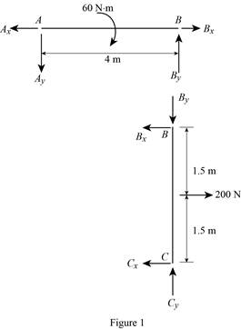
A person exerts 60 N forces on the handles of locking ... Mechanical Engineering questions and answers. A person exerts 60 N forces on the handles of locking wrench. DE is a two-force member. GON 8 mm 40mm C bomm 30mm 75mm LON 1. (5 points). Draw a free body diagram of the handle CD. 2. (5 points). Calculate the reaction force at point C. 3. (5 points). Draw a free body diagram of the member ABC.
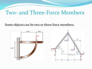
Two- and Three-Force Members
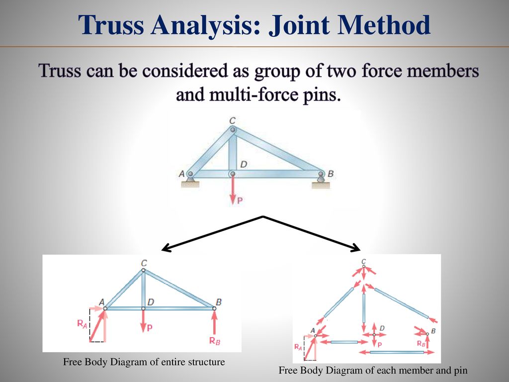
Two- and Three-Force Members - Massachusetts Institute of ... The free body diagram of the system can be seen in the diagram below. The magnitude and the line of action of the force at F, 10 Kips, is known. and opposite to the force C of the two-force member CB. The line of action of the forces at point F and point C intersect at X. The line of action (Why is this?)

Statics eBook: Two- and Three-Force Members
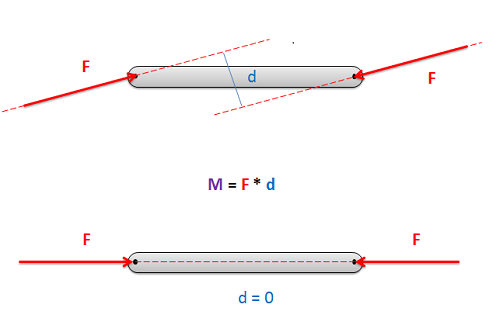
PDF Concepts of Stress and Strain - University of Arizona Consider the following free body diagram of a two-force member. Inasmuch as the stress σ acts in a direction perpendicular to the cut surface, it is referred to as a NORMAL stress. Thus, normal stressed may be either tensile or compressive. Our sign convention for normal stresses is: Tensile stresses are positive (+)

Free body diagram of an arbitrary link 'i ' of the chain, (a ...
PDF Example 1 - Etu note that BC is a two-force membersince only two forces act on it. For this reason, the reaction at C must be horizontal as shown. Since BA and BD are also two-force members, the free-body diagram of joint B is shown in Fig. 1-7c.Again, verify the magnitudes of the computed forces and Free-Body Diagram.Using the result for the left section AG
5.2: Two-Force Members - Engineering LibreTexts
Three-force member free body diagram for ECD | Download ... Download scientific diagram | Three-force member free body diagram for ECD from publication: On the use of three-force member concept versus equilibrium equations in Statics | Use of three-force ...
Chpapter 5 TRUSSES FRAMES AND MACHINES Engineering Mechanics
Two force members explained (statics) - YouTube This engineering statics tutorial explains what two force members are and how they can be used to solve frames, machines, and truss problems. Basically, if a...
Static Analysis Static Analysis, Internal Forces, Stresses ...
PDF ENGR-1100 Introduction to Engineering Analysis FREE-BODY DIAGRAMS (Section 5.2) 2. Show all the external forces and couple moments. These typically include: a) applied loads, b) support reactions, and, c) the weight of the body. Idealized model Free-body diagram (FBD) 1. Draw an outlined shape. Imagine the body to be isolated or cut "free" from its constraints and draw its outlined shape.

Three-force member free body diagram for total use geometric ...
Manual - ODE May 14, 2019 · Then force is apply to the center of mass of each body and the orientation of the force vector is along the axis of the piston. Fixed The fixed joint maintains a fixed relative position and orientation between two bodies, or between a body and the static environment.
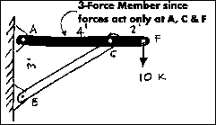
Two- and Three-Force Members
Shear and moment diagram - Wikipedia The first step obtaining the bending moment and shear force equations is to determine the reaction forces. This is done using a free body diagram of the entire beam. The beam has three reaction forces, R a, R b at the two supports and R c at the clamped end. The clamped end also has a reaction couple M c. These four quantities have to be ...
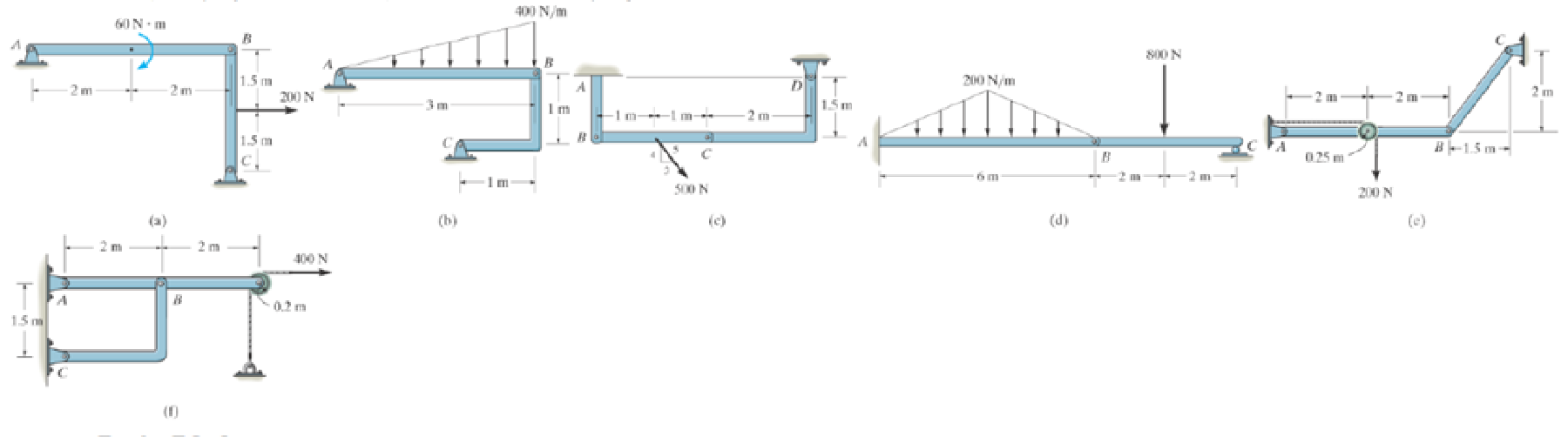
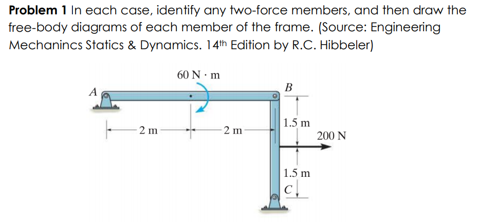
In each case, identify any two-force members, and then draw ...
Solved û D 3 ft E B C 5 ft A 4 ft 6 ft û Figure 2: 200lb ... 1. Draw the free body diagram of the entire system, indicating the reaction forces at the clamped base A clearly. 2. Identify that BD is a two force member and draw the free body diagrams of the. Question: û D 3 ft E B C 5 ft A 4 ft 6 ft û Figure 2: 200lb mass suspended as a trap using a jig. Follow the following process to determine the ...

Trusses - Statics | Coursera
Chapter 5.4 - Two- and Three-Force Members - YouTube Chapter 5.4one example solving a problem of a member being supported by a cable using a free-body diagram and calculating the support reactions

Example 4
PDF Free Body Diagrams - The University of Memphis 2 3 Free Body Diagrams Wednesday, October 3, 2012 Tools ! Algebra ! Trigonometry ! Force components ! Unit Vectors ! Moments 4 Free Body Diagrams Wednesday, October 3, 2012 Review ! When we looked at equilibrium earlier, we used ... connecting two members . 19 37 Free Body Diagrams Wednesday, October 3, 2012 New Support Conditions

PDF) Chapter 5 Equilibrium of a rigid body | alvick lau ...
Question about a simple free body diagram | Physics Forums Jan 15, 2022 · One normally puts only one free body in a free body diagram. Things get cluttered when you have three bodies. A proper free body diagram could let you see that there is no leftward force acting on the right-hand mass ##m## and that there is a net leftward force acting on the big mass ##M##. It follows that the two will separate at least ...

Confusion about two-force members - Physics Stack Exchange
PDF College of Engineering and Computer Science | Wright State ... In each case, identify any two-force members, and draw the free-body diagrams of each member of the E-žme. 60 N m 1.5 m 200 N 1.5 m 400 N /m

a) Identify ALL zero-force members, if any, in the tw… - ITProSpt
What are Free Body Diagrams? - MIT Everything that is needed to solve a force system is included on the FBD. Free body diagrams may not seem necessary in the relatively simple current applications, but as problems become more complex, their usefulness increases. The following is the process for determining the reaction at the wall for a cantilever beam.
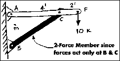
Two- and Three-Force Members
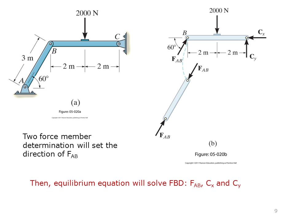
PDF Lecture 23 - Rensselaer Polytechnic Institute 1. Draw a FBD of the frame and its members, as necessary. Hints: a) Identify any two-force members, b) Note that forces on contacting surfaces (usually between a pin and a member) are equal and opposite, and, c) For a joint with more than two members or an external force, it is advisable to draw a FBD of the pin. FAB

For the frame and loading shown, draw the free-body diagram(s ...
PDF Equations of Equilibrium & Two- and Three-force Members TWO-FORCE MEMBERS & THREE FORCE-MEMBERS (Section 5.4) The solution to some equilibrium problems can be simplified if we recognize members that are subjected to forces at only two points (e.g., at points A and B). If we apply the equations of equilibrium to such a member, we can quickly determine that the resultant forces at A and B must

Two-force members | C3.1 Introduction to Plane Trusses | Statics
Question about a simple free body diagram | Page 2 ... sysprog said: the second diagram is a free-body diagram; No, it's not. A free body diagram contains only one body, and it shows all the forces acting on that one body. To analyze a situation with more than one body, you draw a separate free body diagram for each body. there is no real apparatus involved -- it's an abstraction;
Free Body Diagram
Free Body Diagrams, Tutorials with Examples and Explanations Example 8 : A system with two blocks, an inclined plane and a pulley. A) free body diagram for block m 1 (left of figure below) 1) The weight W1 exerted by the earth on the box. 2) The normal force N. 3) The force of friction Fk. 4) The tension force T exerted by the string on the block m1. B) free body diagram of block m 2 (right of figure below)

In each case, identify any two force members, and then draw ...
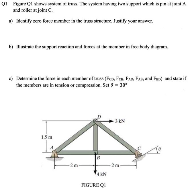
SOLVED:Q1 Figure QI shows system of truss. The system having ...

Consider the following frame. The weight of the suspended ...
Three-Force Member Example Problem
Chapter 6 Structural Analysis Section 6.6 FRAMES AND MACHINES
Mechanics Map - Two Force Members
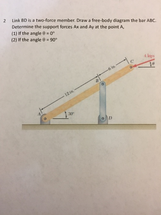
Solved 2 Link BD is a two-force member. Draw a free-body ...
In each case, identify any two-force members, and then draw ...

5.4 Two- and Three-Force Members - ppt video online download
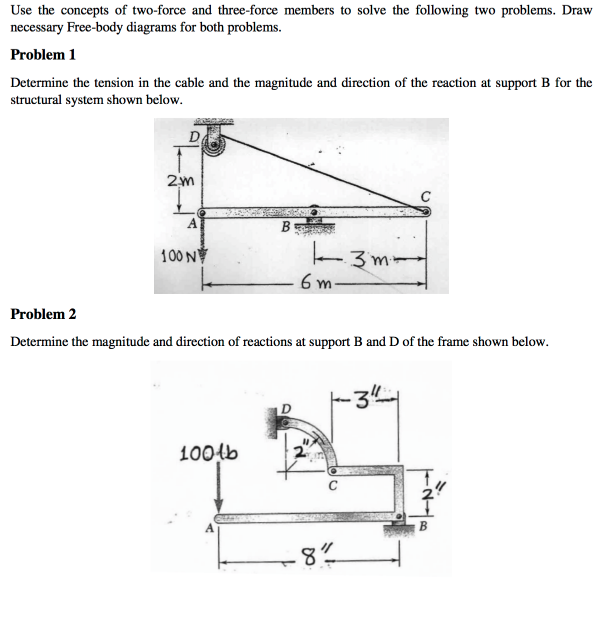
Solved Use the concepts of two-force and three-force members ...
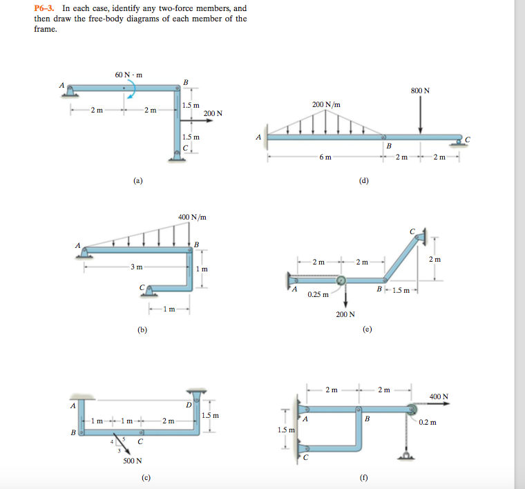
Solved Identify any two force members and then draw the free ...

Chapter Objectives Chapter Outline Rigid body diagram FBD and ...
Free body diagrams
F Pin B F Pin B
EQUATIONS OF EQUILIBRIUM & TWO- AND THREE-FORCE MEMBERS
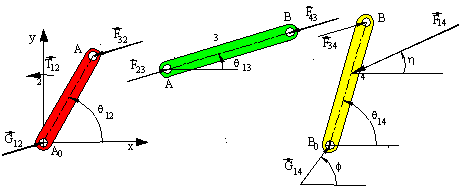
STATIC FORCE ANALYSIS

Page 347 - เรื่อง โปรแกรมช่วยคำนวณกลศาสตร์วิศวกรรม(ภาคสถิต ...

Truss | PDF | Truss | Force
5.2 Method of Joints – Engineering Mechanics: Statics
Answered: Problem 1 In each case, identify any… | bartleby
0 Response to "39 Two Force Member Free Body Diagram"
Post a Comment