38 tanabe sugano diagram d8
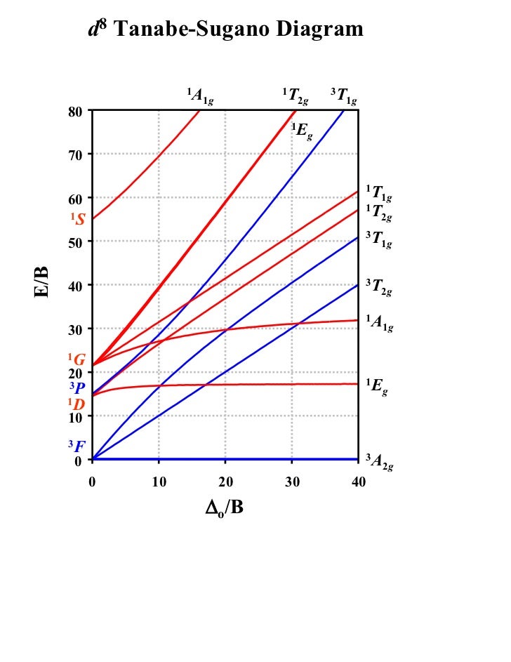
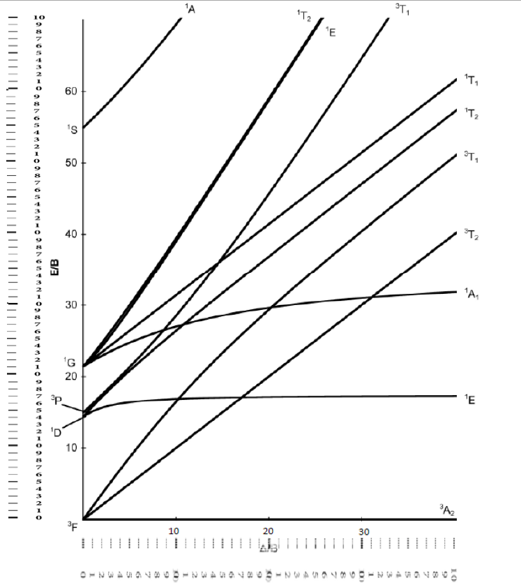
Notes on d7 Tanabe-Sugano Diagram!The d 7 diagram, like all such diagrams for configurations that may be either high spin or low spin, has a perpendicular line near the middle marking the change in spin state. "To the left of the line (low field strength, high spin), the ground state is 4T 1, emerging from the free-ion 4F term. For the octahedral d 8 case, the ground term is 3 A 2g which is plotted along the X-axis. The first spin-allowed transition is to the 3 T 2g level which is the red line. The second spin-allowed transition is to the 3 T 1g level (drawn in blue) and the third transition is to the 3 T 2g (P) level (drawn in green).
Certain Tanabe-Sugano diagrams (d 4, d 5, d 6, and d 7) also have a vertical line drawn at a specific Dq/B value, which is accompanied by a discontinuity in the slopes of the excited states' energy levels.This pucker in the lines occurs when the identity of the ground state changes, shown in the diagram below. The left depicts the relative energies of the d 7 ion states as functions of ...
Tanabe sugano diagram d8
田辺・菅野ダイアグラム (たなべ・すがのダイアグラム、Tanabe-Sugano diagram)は、第4周期 dブロック元素 の正八面体型 錯体 における 結晶場 あるいは 配位子場 の強さと各 スペクトル項 のエネルギーの相関を表した グラフ のことである。 1954年に 田辺行人 と 菅野暁 によって提唱された。 目次 1 概要 2 応用 3 背景 4 分裂 5 田辺・菅野ダイアグラム 6 参考文献 7 関連項目 概要 田辺・菅野ダイアグラムは横軸に配位子場の強さ Dq (配位子場分裂の大きさ) (またはΔ o )を ラカーパラメータ Bで割った値、縦軸に各スペクトル項の基底状態とのエネルギー差EをBで割った値をとり、各スペクトル項についてプロットしたものである。 For the octahedral d 8 case, the ground term is 3 A 2 g which is plotted along the X-axis. The first spin-allowed transition is to the 3 T 2 g level which is the red line. The second spin-allowed... d7Tanabe-Sugano Diagram E / B ∆o/ B 4F 2G 2Eg 2T1g 2A1g 2T2g 4P 4A 2g 4T 1g ( 4P) 4T 2g 4T 1g ( 4F) Complexes with d4-d7 electron counts are special •at small values of ∆o/B the diagram looks similar to the d2diagram •at larger values of ∆o/B, there is a break in the diagram leading to a
Tanabe sugano diagram d8. Tanabe-Sugano diagram for inorganic laboratory students Lecture 4 May 11: Tanabe Sugano Diagrams A Tanabe-Sugano (TS) diagram plots the energy dependence of the various ligand field states (or terms) with field strength. The strength of the ligand field is defined by Dq, which is related to the octahedral crystal field splitting by 10Dq = ∆o. The energy of the state is given by E. Using a Tanabe-Sugano diagram for a d3 system this ratio is found at Δ/B= Tanabe-Sugano diagram for d3 octahedral complexes Interpolation of the graph to find the Y-axis values for the spin-allowed transitions gives. d2 Tanabe-Sugano diagram. d3 Tanabe-Sugano diagram. d4 Tanabe-Sugano diagram. d5 Tanabe-Sugano diagram. A series of JAVA applets of Tanbe-Sugano diagrams were developed by Prof. Robert Lancashire at the University of the West Indies. These diagrams allow students to determine delta o /B values based on ratios of peak energies without the pain of rulers and drawing lines. There are also features that allow a person to input values and automatically calculate certain parameters.
There is no low-spin or high-spin designation for d2, d3, or d8 All of prepared Ni(II) complexes are d8 and have 3 d-d transitions Summary Definition of Tanabe-Sugano diagrams How to determine the d-d transition for metal ion Tanabe-Sugano diagrams for HS & LS in Oh geometry References Inorganic chemistry, Shriver and Atkins, fifth edition ... Tanabe-Sugano diagram에서 실제로, B 값을 구할 수 있는데요. 이 값이 크면 그만큼 불안정하다는 것이고, 작으면 안정하다는 것으로 해석하시면 됩니다. 그리고, 책 혹은 Tanabe-Sugano diagram에서 Nephelauxetic Effect 네팔로제릭 효과라는 게 등장하는데요. Interpretation of the Tanabe Sugano diagram. We can estimate the value of Δ and B from Tanabe Sugano diagram. For example Ni2+ which is has the electronic configuration of d8. So, by referring the d8 Tanabe Sugano diagram, we can can noticed that there are 3 types of transition. The transitions are observed as V1=8500cm-1, V2=13800cm-1 and v3 ... Full matrices in the form of spreadsheets are provided in this paper for octahedral and tetrahedral symmetry for all cases from d2 through d8. Diagonalization of such matrices with MACSYMA is illustrated. Construction of full Tanabe-Sugano diagrams is possible for students for any choice of input parameters. Download to read the full article text.
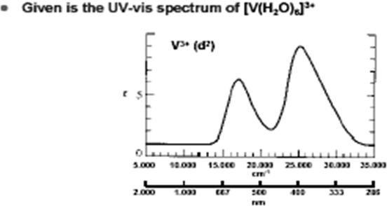
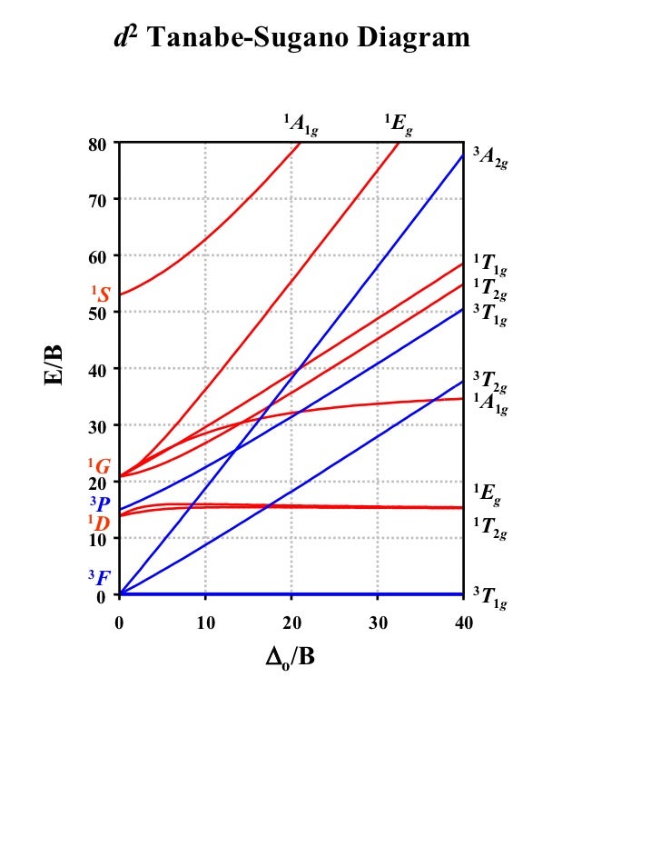
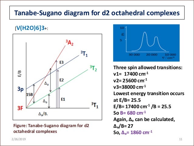
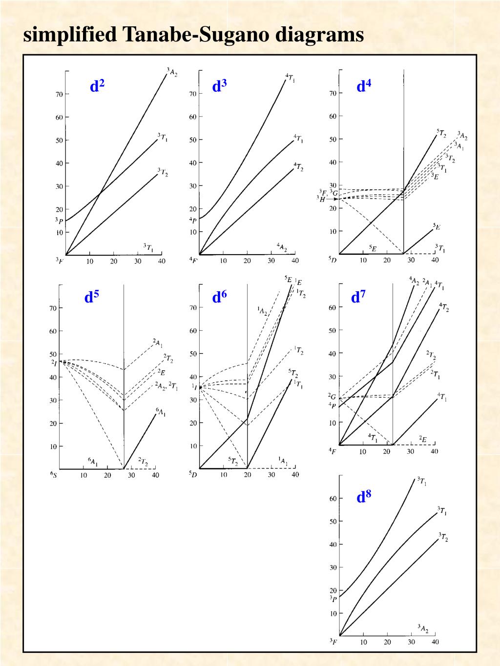
d2Tanabe-Sugano Diagram E / B ∆o/ B 3F 3P 3T 1g (3P) 3A 1g 3T 2g (3F) 3T 1g ~15B ~∆o ~∆o E1 E2 E3 E is the energy of the excited state relative to the ground state B is the Racah parameter for e--e-repulsion The example on page 427 of your text shows how to use this chart to fit the experimental data (E1, E2, and E3) for [V(OH2)6]3+to ... d8 Tanabe-Sugano Diagram 1A 1T 3T 1g 2g 1g 80 1E g 70 1T 60 1T 1g 1S 2g 3T 50 1g E/B 3T 40 2g 1A 30 1g 1G 20 1E 3P g 1D 10 3F 3A 0 2g 0 10 20 30 40 ∆o/B 8. d2 ν2/ν1 Ratio 2.6 2.4 2.2 2.0 ν2/ν1 1.8 1.6 1.4 1.2 10 15 20 25 30 35 40 ∆/B ... The Orgel and Tanabe-Sugano diagram for d8-configuration can be used to estimate the value of crystal field splitting energy for these transition metal complexes. (a) (b) Figure 39. The (a) Orgel and (b) Tanabe-Sugano diagrams for d8complexes in the octahedral crystal field. Consider the example of [Ni(H2O)6]2+. 1. Orgel and Tanabe-Sugano Diagrams for Transition Metal Complexes (d1 - d9 States) It is a well-known fact that electronic transitions are always accompanied by vibrational as well as rotational changes which results in a considerable broadening of the bands in the UV-visible spectra of transition metal complexes too.
green and yellow map
잘 찾아보시면 d1과 d9의 Tanabe - Sugano diagram을 찾아보는 것은 쉽지 않을 것입니다. 그 이유는 필요가 없기 때문이죠. 즉, 특정 E를 쏴주면 딱 1개의 peak만 UV-VIS spectrum에 표시가 될 것입니다. 그러면 그 E 값이 바로 LFSE가 됩니다. (2) d3, d8 d3과 d8의 전자배치를 보겠습니다.

D8 Tanabe Sugano Diagram
Description. Tanabe Sugano Diagram d8.svg. English: The Tanabe-Sugano diagram for a d 8 transition metal ion. The energies are calculated using a Racah C = 4.5 B, and only selected states are depicted. Transitions from the triplet ground state to singlet excited states (dotted) are spin-forbidden.

Student Notebook Containing Notes, Diagrams and Swatches (c. 1898–1900) // Alfred Fehr (Switzerland, 1879-1955)
Tanabe sugano diagram 1. PRESENTED BY: Khondaker Afrina Hoque. ID-1114015, Reg:900048 Department of chemistry. Comilla university 2/26/2019 1 2. TANABE-SUGANO DIAGRAM 2/26/2019 2 3. Introduction Background: • Yukito Tanabe and satoru sugano- " On the Absorption spectra of complex ions"-1954.
unknown
Tanabe-Sugano Diagram - Parameters Parameters The x-axis of a Tanabe-Sugano diagram is expressed in terms of the ligand field splitting parameter, Dq, or Δ, divided by the Racah parameter B. The y-axis is in terms of energy, E, also scaled by B. Three Racah parameters exist, A, B, and C, which describe various aspects of interelectronic repulsion.

(a) Tanabe-Sugano diagrams for Co 2 + (d 7 ; T d ) using ...
TANABE-SUGANO DIAGRAMS An alternative method is to use Tanabe Sugano diagrams, which are able to predict the transition energies for both spin-allowed and spin-forbidden transitions, as well as for both strong field (low spin), and weak field (high spin) complexes.

Dymaxion Car, Section (1933) // Richard Buckminster Fuller American, 1895-1983
• Tanabe-Sugano diagrams have been calculated for d the cases of all ligand field strengths for all octahedral dn-metal complex configurations. • The diagrams allow for estimation of a complete set of parameters included in the calculations: i) the (apparent) electron repulsion parameter B', ii) D, iii) transition frequencies. 52
chair parts chart hanging on wall
A Tanabe-Sugano diagram of the spin-allowed and some forbidden transitions for octahedral d8 and tetrahedral d2 complexes is given below. 1580s, "to make a map or diagram of, lay down on paper according to scale;" also "to lay plans for, conspire to effect or bring about" (usually with evil intent), from plot (n.). Intransitive sense of "to form a plan or device" is from c. 1600.

13 Tanabe Sugano Diagrams - 5.04, Principles of Inorganic ...
D8 Tanabe Sugano Diagram The different free ion terms for an electron configuration have different energies due to variations in electron-electron repulsion. The different. Tanabe-Sugano diagrams are used in coordination chemistry to predict absorptions in the UV, . d8 Tanabe-Sugano diagram. d8 electron configuration .
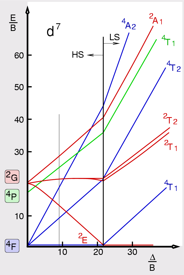
Abb. I.2.9. Terme für d 7 -Systeme ‣ SVG
d2 Tanabe-Sugano Diagram 1A 1E 1g g 80 3A 2g 70 60 1T 1g 1T 1S 2g 3T 50 1g E/B 40 3T 2g 1A 1g 30 1G 20 1E 3P g 1D 1T 2g 10 3F 3T 0 1g ∆o/B 0 10 20 30 40 d3 Tanabe-Sugano Diagram 4T 2 1g A2g 80 70 2A 1g 4T 60 1g 50 4T 2g E/B 40 2F 2T 2g 30 2T 1g 20 2E 2G g 4P 10 4F 4A 0 2g ∆o/B 0 10 20 30 40 50 d4 Tanabe-Sugano Diagram 3A 1 2g A2

D8 Tanabe Sugano Diagram
A step-by-step tutorial on assigning the transitions in the UV-vis spectrum of a d7 system using a Tanabe-Sugano Diagram.

A Tanabe-Sugano diagram for the Fe 2+ ion (3d 6 ...
d7Tanabe-Sugano Diagram E / B ∆o/ B 4F 2G 2Eg 2T1g 2A1g 2T2g 4P 4A 2g 4T 1g ( 4P) 4T 2g 4T 1g ( 4F) Complexes with d4-d7 electron counts are special •at small values of ∆o/B the diagram looks similar to the d2diagram •at larger values of ∆o/B, there is a break in the diagram leading to a
D6 Tanabe Sugano Diagram
For the octahedral d 8 case, the ground term is 3 A 2 g which is plotted along the X-axis. The first spin-allowed transition is to the 3 T 2 g level which is the red line. The second spin-allowed...

Tanabe-Sugano diagram for octahedrally coordinated V 3 ...
田辺・菅野ダイアグラム (たなべ・すがのダイアグラム、Tanabe-Sugano diagram)は、第4周期 dブロック元素 の正八面体型 錯体 における 結晶場 あるいは 配位子場 の強さと各 スペクトル項 のエネルギーの相関を表した グラフ のことである。 1954年に 田辺行人 と 菅野暁 によって提唱された。 目次 1 概要 2 応用 3 背景 4 分裂 5 田辺・菅野ダイアグラム 6 参考文献 7 関連項目 概要 田辺・菅野ダイアグラムは横軸に配位子場の強さ Dq (配位子場分裂の大きさ) (またはΔ o )を ラカーパラメータ Bで割った値、縦軸に各スペクトル項の基底状態とのエネルギー差EをBで割った値をとり、各スペクトル項についてプロットしたものである。
Interpretation of the spectra of first-row transition ...

The actor Segawa Kikunojo III as Oshizu, wife of Tanabe Bunzo (1794) // Toshusai Sharaku æ±æ´²æ–Ž 写楽 Japanese, active 1794-95
human heart scale model
Tanabe Sugano Diagrams - Chemistry LibreTexts
T sdiagram
T sdiagram

Tanabe-Sugano diagram for the d 5 electron configuration ...
Solved: 2) Use The Attached Tanabe-Sugano Diagram To (i) E ...
Tanabe sugano diagram

6. Partial d 8 Tanabe-Sugano diagram relevant to ...

white animal skull on white surface

white pasta on white paper

Club de Centre Rural: Perspective Sketch (1943) // Le Corbusier French, born Switzerland, 1887-1965

35 Tanabe Sugano Diagram - Wiring Diagram Database

Tanabe Sugano | Coordination Complex | Quantum Mechanics ...
D8 Tanabe Sugano Diagram
PPT - Electronic (UV-visible) Spectroscopy PowerPoint ...
navigation map

Diagramas de Tanabe-Sugano :: QuiPad
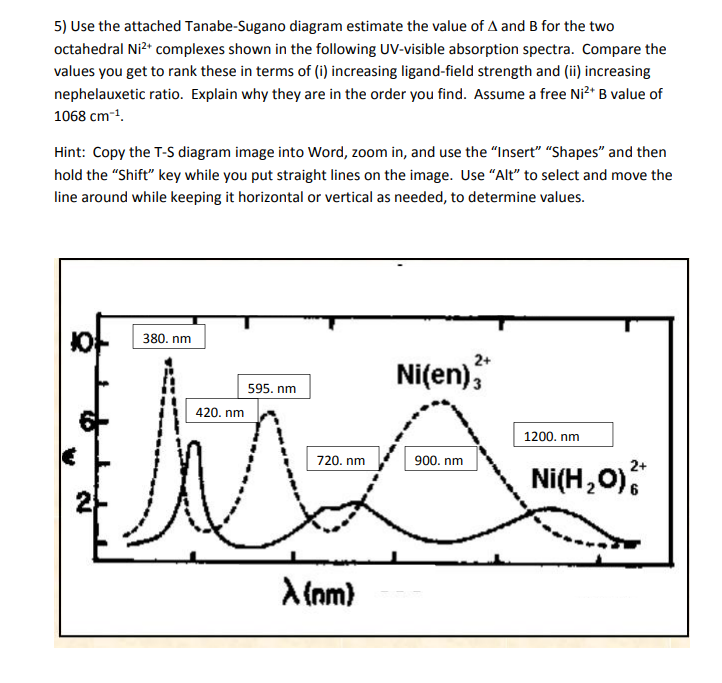
Solved: 5) Use The Attached Tanabe-Sugano Diagram Estimate ...

Tanabe-Sugano diagram for the d 8 electron configuration ...

River City, Aerial Perspective (1979) // Bertrand Goldberg American, 1913–1997
![The Tanabe-Sugano diagram (from [6]) for tetrahedral (left ...](https://www.researchgate.net/profile/A_Gavriliuk/publication/226349110/figure/download/fig3/AS:302232575725574@1449069269561/The-Tanabe-Sugano-diagram-from-6-for-tetrahedral-left-and-octahedral-right.png?_sg=USzXuJCnKL69tW5CMh358y7weIJmu0BK9yKnJnNJcHHrDbo8sCRQ3hbVbgMiJk1Xfe-DPaTm-hg)
The Tanabe-Sugano diagram (from [6]) for tetrahedral (left ...
Diagramas de Tanabe-Sugano :: QuiPad

Mobile Delousing Unit, Truck Equipment, Plan of Operation and Erection Procedure, Presentation Drawing (1943) // Bertrand Goldberg American, 1913-1997
0 Response to "38 tanabe sugano diagram d8"
Post a Comment