38 draw a proper free body diagram for the curved bar shown below.
• The disk shown in the figure rolls without slipping on a horizontal plane. Attached to the disk through a frictionless hinge is a massless pendulum of length L that carries another disk. The disk at the bottom of the pendulum cannot rotation relative to the pendulum arm. • Draw free-body diagrams and derive equations of motion for this ... Example 8 : A system with two blocks, an inclined plane and a pulley. A) free body diagram for block m 1 (left of figure below) 1) The weight W1 exerted by the earth on the box. 2) The normal force N. 3) The force of friction Fk. 4) The tension force T exerted by the string on the block m1. B) free body diagram of block m 2 (right of figure below)
A differential element taken from a curved bar is shown in the figure. Show that dN/dθ = V, dV/dθ = N, dM/dθ = T, and dT/dθ = M. View Answer A curved bar ABC having a circular axis (radius.) is loaded by forces P = 400lb (see figure).

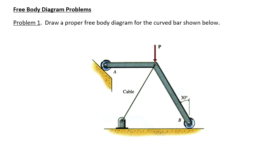
Draw a proper free body diagram for the curved bar shown below.
For this reason, the reaction at C must be horizontal as shown. Since BA and BD are also two-force members, the free-body diagram of joint B is shown in Fig. 1-7c.Again, verify the magnitudes of the computed forces and Free-Body Diagram.Using the result for the left section AG of the beam is shown in Fig. 1-7d. Equations of Equilibrium. Experts are tested by Chegg as specialists in their subject area. We review their content and use your feedback to keep the quality high. Transcribed image text: Free Body Diagram Problems Problem 1 (10 points) Draw a proper free body diagram for the curved bar shown below. Cable. Drawing Free-Body Diagrams. Free-body diagrams are diagrams used to show the relative magnitude and direction of all forces acting upon an object in a given situation. A free-body diagram is a special example of the vector diagrams that were discussed in an earlier unit. These diagrams will be used throughout our study of physics.
Draw a proper free body diagram for the curved bar shown below.. 4. Draw a proper free body diagram for the curved bar shown below. Write force balance equations (using symbols) for both the x and y directions. Question: 4. Draw a proper free body diagram for the curved bar shown below. Write force balance equations (using symbols) for both the x and y directions. Draw a proper free body diagram for the curved bar shown below. View Answer What is the acceleration of an automobile of mass 1.40 × 10³ kg when it is subjected to a forward force of 3.36 × 10³ N? Draw a proper free body diagram for the curved bar shown below. Problem 2. Draw a proper free body diagram for the cart of weight W shown below. Cable . This problem has been solved! See the answer See the answer See the answer done loading. Show transcribed image text Expert Answer. Statics (MET 2214) Free-Body Diagram (FBD): To apply equilibrium equations we must account for all known and unknown forces acting on the particle. The best way to do this is to draw a free-body diagram of the particle. FBD: A diagram showing the particle under consideration and all the forces and moments acting on this particle.
Free Body Diagrams and Particle Statics Problem 1. Draw a proper free body diagram for the curved bar AB shown below. Assume absence of friction in the problem. [15 points] Free body diagram with all external forces and necessary geometric entities = 15 points (Partial credit for missing ... Draw a proper free body diagram for the curved bar shown below. View Answer. Susie hammers on a block of wood 85 m from a large brick wall. Each time she hits the block, she hears an echo 0.5 s later. With this information, show that the speed of sound is 340 m/s. Hibbeler chapter5. 1. Engineering Mechanics - Statics Chapter 5 Problem 5-1 Draw the free-body diagram of the sphere of weight W resting between the smooth inclined planes. Explain the significance of each force on the diagram. Given: W = 10 lb θ 1 = 105 deg θ 2 = 45 deg Solution: NA, NB force of plane on sphere. W force of gravity on sphere. Question: Draw a proper free body diagram for the curved bar shown below. This problem has been solved! See the answer ...
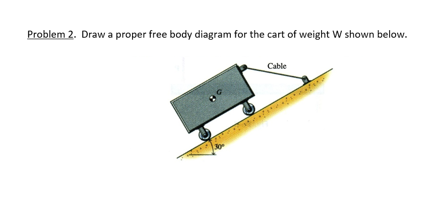
Draw a proper free body diagram for the curved bar AB shown below. Assume absence of friction in the problem. [15 points] Free body diagram with all external forces and necessary geometric entities = 15 points (Partial credit for missing components) Problem 2. Draw a proper free body diagram for the cart of weight W shown below. ENGINEERING MECHANICS - STATICS, 2nd. Ed. W. F. RILEY AND L. D. STURGES. 6-5 Draw a free-body diagram for the curved bar shown in Fig. P6-5. Answer to For the shaft shown below, draw the free body Draw a proper free body diagram for the curved bar shown below. Draw a proper free body diagram for the cart of weight W shown below. Question: Draw a proper free body diagram for the curved bar shown below. Draw a proper free body diagram for the cart of weight W shown below.
Draw a proper free body diagram for the curved bar shown below. Problem 2. Draw a proper free body diagram for the cart of weight W shown below. Cable . This problem has been solved! See the answer See the answer See the answer done loading. Show transcribed image text Expert Answer.
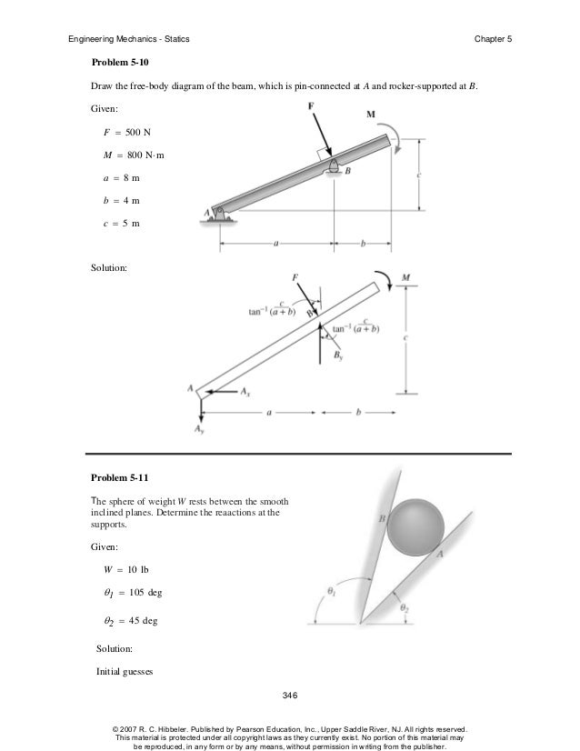
Hibbeler chapter5
To draw a free body diagram, start by sketching a simple representation of the body you want to make the diagram of, like a square to represent a box. Next, draw arrows on the shape that show the forces acting on the object. For example, draw a downward arrow to signify the weight of the object, since gravity pulls the object down.

Eckhard Bick - PDF Free Download
Advanced Physics questions and answers. Free Body Diagram Problems Problem 1. Draw a proper free body diagram for the curved bar shown below. 6-7 The curved bar shown in Fig. P6-7. Problem 2. Draw a proper free body diagram for the cart of weight W shown below. 6-11 The cart shown in Fig. P6-11, which has a weight W. Cable.

FREE Answer to For the shaft shown below, draw the free body diagram of just the shaft (isolated from...
Solved: Draw A Proper Free Body Diagram For The Curved Bar ...
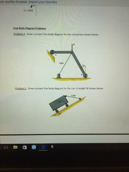
ENGR 112 - Spring 2016 - Class 13 Statics 1 Free Body Diagrams and Particle Statics Problem Set Free Body Diagram Problems Problem 1. Draw a proper free body diagram for the curved bar shown below. Problem 2. Draw a proper free body diagram for the cart of weight W shown below.
Kenya's local content promotion website: August 2009
SHOW ALL WORK Ensure you are following the Problem Solving Methodology discussed in class to maximize credit: Free Body Diagram Problems Problem 1 (10 points) Draw a proper free body diagram for the curved bar shown below.

Dedicated to Ashley & Iris - Документ
Who are the experts? Experts are tested by Chegg as specialists in their subject area. We review their content and use your feedback to keep the quality high. 100% (32 ratings) Transcribed image text: Draw a proper free body diagram for the curved bar shown below. Draw a proper free body diagram for the cart of weight W shown below.

Dedicated to Ashley & Iris - Документ
of bars of the truss and the total number of external support ... joint's free body diagram to be in tension ... whereas a negative answer indicates that the sense shown on the free-body diagram must be reversed. Example 3.2 Determine the force in each member of the roof truss as shown. State

Solved: Chapter 5 Problem 5P Solution | Engineering ...
The beam shown below is supported by a pin at A and roller at B. Calculate the reactions at both supports due to the loading. 20 kN 40 kN 2 m 3 m 4 m A B EXAMPLE 1 . Draw the free body diagram: By taking the moment at B,

Michael Heath-Caldwell M.Arch - 1948 Journal for the Use ...
Draw a proper free body diagram for the curved bar shown below. View Answer. Draw the free body diagrams of the two spur gears shown in Figure. Use the resulting equations of motion to show that T2 = NT1 if the gear inertias are negligible or if there is zero acceleration.

Dedicated to Ashley & Iris - Документ
2-17 SOLUTION (2.14new) Known: The geometry and the loads acting on a pinned assembly are given. Find: Draw a free-body diagram for the assembly and determine the magnitude of the forces acting on each member of the assembly. Schematic and Given Data: 45˚ 45˚ 1000 mm 1500 N 1500 N 45˚ 45˚

Often a Free Body Diagram is useful or necessary to solve a problem that involves forces. Follow these steps, and you'll solve any problem with little difficulty. 1. Draw one Free Body Diagram for each object (see below for what is a good FBD). 2. Break the forces up into components. 3.
Chapter 6 Drawing A Free-Body Diagram: Readings And Exercises. Course:Mechanics of material (MOM) T he free-body diagram is the most im-portant tool in this book. It is a drawing of a. system and the loads acting on it. Creating. a free-body diagram involves mentally sep-

Michael Heath-Caldwell M.Arch - 1964 `1964Rev. Capt C.H ...
Drawing Free-Body Diagrams. Free-body diagrams are diagrams used to show the relative magnitude and direction of all forces acting upon an object in a given situation. A free-body diagram is a special example of the vector diagrams that were discussed in an earlier unit. These diagrams will be used throughout our study of physics.
Solved: Draw A Proper Free Body Diagram For The Curved Bar ...
ENGR 112 - Spring 2016 - Class 13 Statics 1 Free Body Diagrams and Particle Statics Problem Set Free Body Diagram Problems Problem 1. Draw a proper free body diagram for the curved bar shown below. Problem 2. Draw a proper free body diagram for the cart of weight W shown below.
Please when you download the pictures tag and follow me on instagram: https://www.instagram.com/emilianovittoriosi/ you will help me to grow up! Thank you!
See the diagram in the lower right of Figure 3-2. Step 2: The set of free-body diagrams is shown in Figure 3-3. Step 3: Now consider the free-body diagrams of all of the members in Figure 3-3. We have already discussed member 1, recog-nizing it as a two-force member in tension carrying forces RA and RC equal to 48.07 kN.
Solved: Draw A Proper Free Body Diagram For The Cart Of We ...
A free-body diagram is a representation of an object with all the forces that act on it. The external environment (other objects, the floor on which the object sits, etc.), as well as the forces that the object exerts on other objects, are omitted in a free-body diagram. Below you can see an example of a free-body diagram:
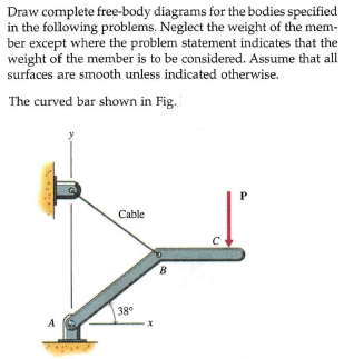
Answered: Draw complete free-body diagrams for… | bartleby
Draw a proper free body diagram for the curved bar shown below.

Step 1: Draw a simple picture (called a Free Body Diagram), and label your axes! Step 2: Identify and draw all force vectors Step 3: Use your drawing to write down Newton's 2nd law F Net = ma T - W 2= 0 In equilibrium, everything is balanced! a = 0 T = W = mg = (5 kg)*(9.8 m/s ) = 49 N +y -y Weight, W Tension, T W T

Mechanical Engineering Archive | October 13, 2015 | Chegg.com
Question: Free Body Diagram Problems Draw a proper free body diagram for the curved bar shown below. This problem has been solved! See the answer ...

Photo taken at my friend’s farm where I stayed for some days at the peak of my depression. This photo, this friend and all this feeling helped me create a transparent and deep photographic material. This photo is melancholia and at the same time peace.
Figure 5.32 (a) The free-body diagram for isolated object A. (b) The free-body diagram for isolated object B. Comparing the two drawings, we see that friction acts in the opposite direction in the two figures. Because object A experiences a force that tends to pull it to the right, friction must act to the left. Because object B experiences a component of its weight that pulls it to the left ...

This problem has been solved! ... Draw a proper free body diagram for the curved bar shown below. Cable 30°. Show transcribed image text. Expert Answer.

Please donate. WebMoney: Z138632687735, R330729825060, skrill- alexfoto@bigmir.net, SWIFT - KRYVYTSKYI OLEKSANDR, BIC: PBANUA2X, IBAN: UA913052990005168745600778382, I will be glad information on the use of photos.
See the diagram in the lower right of Figure 3–2. Step 2: The set of free–body diagrams is shown in Figure 3–3. Step 3: Now consider the free-body diagrams of all of the members in Figure 3–3. We have already discussed member 1, recog-nizing it as a two–force member in tension carrying ...

Answered: Free Body Diagrams and Particle Statics ... |24HA
Draw the free body diagrams of the two spur gears shown in Figure. Use the resulting equations of motion to show that T2 = NT1 if the gear inertias are negligible or if there is zero acceleration. Here T2 is taken to be the torque felt on shaft 2 due to the applied torque T1. View Answer

ENGR 216 SPRING 2020 Homework 4 Free Body Diagrams and Particle Statics DUE by End of Day Friday, 4/3/20 Free Body Diagram Problems Problem 1. Draw a proper free body diagram for the curved bar shown below. Problem 2. Draw a proper free body diagram for the cart of weight W shown below.

I will be glad information on the use of photos. I would be very grateful for the donation replenishment of my phone +380991680050
Draw a proper free body diagram for the curved bar shown below. View Answer A person sitting in an enclosed train car, moving at constant velocity, throws a ball straight up into the air in her reference frame.

(15 points) Draw a proper free body diagram for the curved bar shown below. Problem 7. (15 points) Draw a proper free body diagram for the cart of weight W shown below. Problem 8. (20 points).

Eating the candy bar increases the amount of sugar in the ...
Drawing Free-Body Diagrams. Free-body diagrams are diagrams used to show the relative magnitude and direction of all forces acting upon an object in a given situation. A free-body diagram is a special example of the vector diagrams that were discussed in an earlier unit. These diagrams will be used throughout our study of physics.

Dedicated to Ashley & Iris - Документ
Experts are tested by Chegg as specialists in their subject area. We review their content and use your feedback to keep the quality high. Transcribed image text: Free Body Diagram Problems Problem 1 (10 points) Draw a proper free body diagram for the curved bar shown below. Cable.

Dedicated to Ashley & Iris - Документ
For this reason, the reaction at C must be horizontal as shown. Since BA and BD are also two-force members, the free-body diagram of joint B is shown in Fig. 1-7c.Again, verify the magnitudes of the computed forces and Free-Body Diagram.Using the result for the left section AG of the beam is shown in Fig. 1-7d. Equations of Equilibrium.

A well defined collarbone is hard to come by.

Fruit Of The Loom
Mechanical Engineering Archive | February 07, 2017 | Chegg.com

Kyiv city fine art
![The Sacred Harp [Machine readable transcription]B.F. White ...](https://archive.lib.msu.edu/AFS/dmc/ssb/public/all/dscbannr.gif)
The Sacred Harp [Machine readable transcription]B.F. White ...

Dedicated to Ashley & Iris - Документ
![[Solved] Draw the free-body diagram for a basketball ...](https://s3.amazonaws.com/si.question.images/images/P-M-L-M(329).PNG)
[Solved] Draw the free-body diagram for a basketball ...

0 Response to "38 draw a proper free body diagram for the curved bar shown below."
Post a Comment