42 dc to dc step up converter circuit diagram
DC-DC converters are also known as choppers.Here we will have a look at Buck Boost converter which can operate as a DC-DC Step-Down converter or a DC-DC Step-Up converter dependingupon the duty cycle, D.. A typical Buck-Boost converter is shown below. The input voltage source is connected to a solid state device. The second switch used is a diode.The diode is connected, in reverse to the ... It seems the DC to DC step up converter is influencing the power source. Also what I'm noting is that the output light seems to be blinking means fast on of visible for the eye. The same I'm seeing on the led's of my power supply for both the voltage and amp-LED.
The circuit mentioned here will perform the task of step down fixed voltage DC to DC converter. There are many fixed voltage DC to DC step down converter ICs are available in the market like LM7805 for DC 5 volt fixed output, LM7809 is for DC 9 volt fixed output etc. But LM317 is a single IC from which you can get any fix output voltage between ...

Dc to dc step up converter circuit diagram
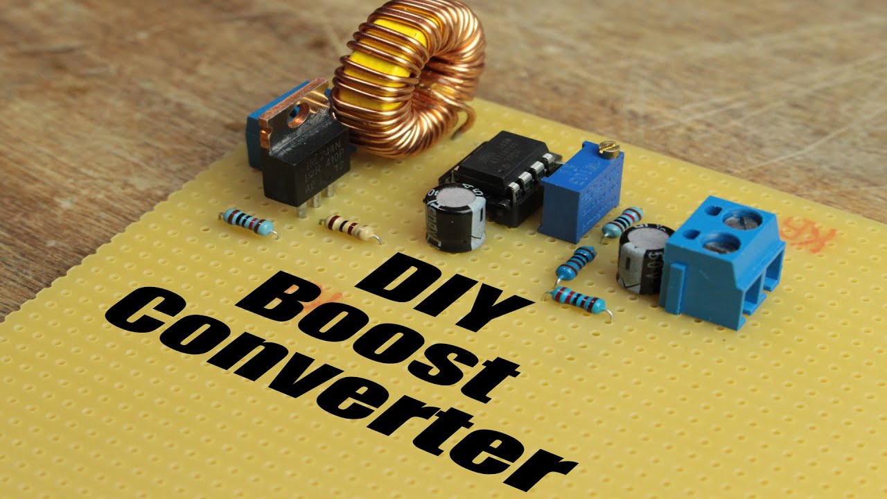
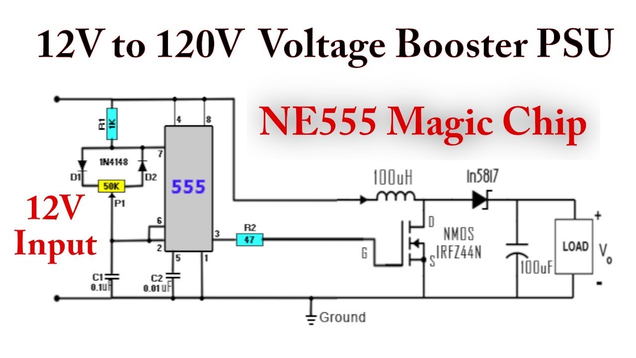
The circuit is divided in to two parts, the first part is a dc to dc step up converter / booster circuit built around a 555 timer ic which boosts the input the second part of the circuit is an adjustable power supply built with lm317 adjustable voltage regulator ic. Jun 30, 2018 - This is usb 5v to 12v dc-dc step-up converter circuit, or Buck DC to DC converters, it using all transistor so easy to builds Hey Engineers, So I am working on revision 2 of a circuit board for a custom snake tank humidifier and light controller project that I am working on, and I wanted to come to reddit for some feedback on the new iteration before I order the boards. The basic overview of the project is that I have a temp/humidity sensor in each tank, and an arduino that watches that data. When humidity falls below a certain level, the arduino turns on an atomizer in a water reservoir, generating mist, which is the...
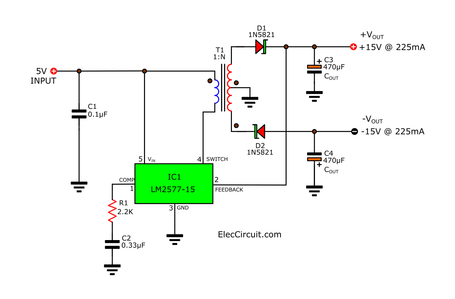
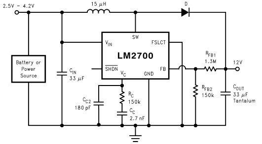
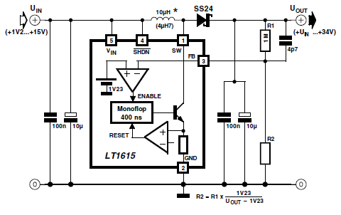
Dc to dc step up converter circuit diagram. The circuit can be assembled on a vero board. Q1 and Q2 require heat sink. Output power of this dc dc converter is around 100 watts. IC1 and IC2 are to be mounted on holders. An optional 5A fuse can be added in series to the 12V supply line. T1 can be a 9-0-9V /250V/3A mains transformer. If 3A bridge is not available make one using 1N5408 diodes. I have gone through and researched lot of DIY UPS projects over youtube and put together these devices. Lot of old spare mobile batteries and 18650s used. Tp5100 and the buck, booster modules are also super cheap to get in the market. Tested both the circuits and i am very happy with the results. Per the circuits, the step-up ( with single li-ion battery will be good for low current consumptions) and the step-down will be enough for raspi 4 current consumptions ( around 2A + ) I elimi... This is the fixed 5V to 12V DC to DC converter. The circuit application converts input voltage of 5V (range 4.5V-5.5v) to 12V fixed regulated DC output. The circuit built based National regulator monolithic IC LM2586 which is specifically designed for flyback, step-up (boost), and forward converter circuit applications. A simple DC to DC step up voltage converter using LM2700 is shown here. LM2700 is a step up switching converter that has a 3.6A, 80 M ohm internal switch. It can be operated at 600 kHz or 1.25MHz switching frequency. In the circuit LM2700 is wired in order to produce 8V DC output from a 3V input at a switching frequency of 600MHz.
**The Circuit** I have almost no knowledge of electrical engineering so please forgive this very unstandardized diagram: https://i.imgur.com/DAKf19p.png Red is for positive, black for ground, and blue for data. In case the diagram proves unreadable, here is a summary of it. I start with 12V DC power which I use a "DC-DC Buck Converter Step Down Module" to convert to 5V. This 5V will power my Arduino Uno and 3 10k potentiometers. In parallel with the RC module is the RGB light which will recei... DC to DC Boost Converter Circuit (Part 5/9) July 1, 2017 By Diksha. Many times, there is need to step up or step down DC voltages. The circuits for stepping up or stepping down DC voltages are not simple as is the case with AC voltages. The level changing of DC voltages requires complex circuitry. These circuits are called DC to DC converters. LM2621 Low Input Voltage, Step-Up DC-DC Converter 1 Features 3 Description The LM2621 is a high efficiency, step-up DC-DC 1• Small VSSOP8 Package (Half the Footprint of Standard 8-Pin SOIC Package) switching regulator for battery-powered and low input voltage systems. It accepts an input voltage between DC to DC Converter Circuits (11) Browse through a total of 11 Some interesing DC/DC converter circuits for 1.5V, ... One Battery to 3 Volts Step-up (Boost) Converter P. Marian - 01/21/2015. With the help of this simple circuit you will be able to convert any voltage between 0.9V and . SCR 12V to 5V USB Converter Jim Keith - 12/23/2014 ...
Step up dc converter circuit for 19v regulation diagram car uc384 laptop charger from 12v battery versatile electronics 15 21v inverter notebook to power supply Step Up Dc Converter Circuit For Laptop Charger Adapter Convert 12v 9 14 To 19v 16 21v Deeptronic 19v Dc Regulation Circuit Diagram Forum For Electronics 12v To 19v Car Dc… Read More » I have gone through and researched lot of DIY UPS projects over youtube and put together these devices. Lot of old spare mobile batteries and 18650s used. Tp5100 and the buck, booster modules are also super cheap to get in the market. Tested both the circuits and i am very happy with the results. Per the circuits, the step-up ( with single li-ion battery will be good for low current consumptions) and the step-down will be enough for raspi 4 current consumptions ( around 2A + ) I eliminated th... This is an lm2596 dc dc buck converter step down power module with high precision potentiometer for adjusting output voltage capable of driving a load up to 3a with high efficiency. When the output current required is greater than 25a10w an external heatsink is suggested. Lm2596 circuit diagram. Typical application circuit for lm2596 5v at 3a ... Hey Engineers, So I am working on revision 2 of a circuit board for a custom snake tank humidifier and light controller project that I am working on, and I wanted to come to reddit for some feedback on the new iteration before I order the boards. The basic overview of the project is that I have a temp/humidity sensor in each tank, and an arduino that watches that data. When humidity falls below a certain level, the arduino turns on an atomizer in a water reservoir, generating mist, which is the...
The circuit for the DC-DC step-down (Buck) converter would have the LM7809 voltage regulator, two capacitors with capacitance value of 0.33µF and 0.1µF. Figure 3 below shows the corresponding circuit, Figure 3: DC-DC step-down (Buck) converter circuit. Step 1: The LM7809 voltage regulator is placed in the desired position on the circuit board.

I have gone through and researched lot of DIY UPS projects over youtube and put together these devices. Lot of old spare mobile batteries and 18650s used. Tp5100 and the buck, booster modules are also super cheap to get in the market. Tested both the circuits and i am very happy with the results. Per the circuits, the step-up ( with single li-ion battery will be good for low current consumptions) and the step-down will be enough for raspi 4 current consumptions ( around 2A + ) I elimi...
Step up voltage converter dc to schematic diagram of a basic boost circuit homemade prototype work circuits 5v 12v Step Up Voltage Converter Dc To Schematic Diagram Of A Basic Step Up Converter Integrated In Scientific Dc To Boost Converter Circuit Homemade Prototype Of Step Up Voltage Converter With Discrete Components Scientific Diagram Dc… Read More »
Critical points in designing DC/DC converter circuits. With SEPIC and Zeta, a capacitor is inserted between V IN and V OUT of the step-up circuit and the step-down circuit of the basic type, and a single coil is added. They can be configured as step-up or step-down DC/DC converters by using a step-up DC/DC controller IC and a step-down DC/DC controller IC, respectively.

Oct 5, 2018 - This is usb 5v to 12v dc-dc step-up converter circuit, or Buck DC to DC converters, it using all transistor so easy to builds
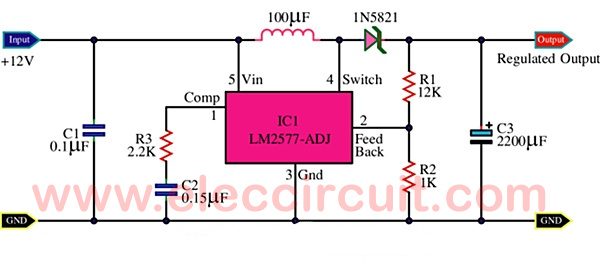
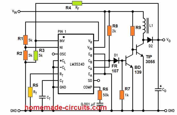
The input voltage of the dc to dc boost converter circuit diagram is 3.5V to 40V DC. You can adjust the output voltage with a 100K variable resistor. The max output voltage of the circuit is 60V DC. You can adjust the output voltage changing input supply and with 100k variable control. The max output current of the circuit is 3A.
Step-Up DC-DC Converter: Effect of Parasitics Parasitic elements are due to losses in the inductor, capacitor, switch, and diode. The duty-ratio is generally limited before the parasitic effects become significant.
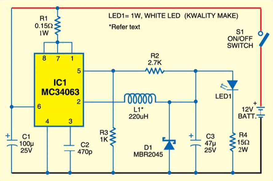
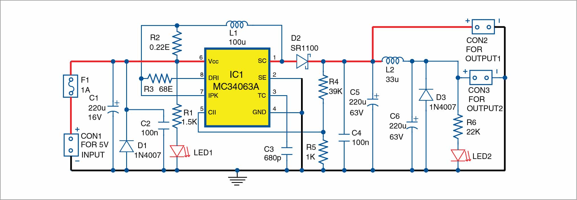
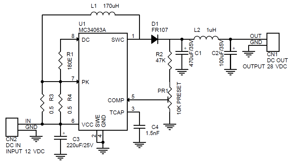
MC34063 is a 1. 5A Step up or step down or inverting regulator, due to DC voltage conversion property, MC34063 is a DC-DC converter IC. Controlled Duty cycle oscillator with an active high current driver output switch. Accept 3.0V to 40V DC. Can be operated at 100 KHz switching frequency with a 2% tolerance.
Hi Everyone, happy 2021 and good riddance to 2020! We (the moderation team) are working on updating the wiki with better guides and resources. With that in mind, I've put together the wiki in this thread, and would like your help in improving it. **Please post any robotics questions you have, and any recommended resources, in the comments. They can be career, educational, technical, beginner or expert.** I'll be updating this post based on the comments, so it's a work in progress. #How to get...

Before I start in to this I want to say I am very safe with everything I am doing. I have worked around electronics my whole life so I know a lot of the safety rules regarding it. All circuits are tested from a large power switch probably 10 yards away on a cement platform. That being said I have never had to design and build one myself and have no clue what I am doing wrong (I have beginner knowledge of DC circuits and little to no experience with ac circuits). I figured my intro to the AC circ...

I'm thinking about first power project for work. We modify portable fridges for medical purposes to have a battery backup (so not mutch space). We currently use self made 2170 3S3P battery packs (120WH) with off the shelf components ("300W" XL4016 CC/CV step down converter for battery charging and "150W" XL6009 step up to maintain 13.2V output from batteries). Currently used solution is not the best because of the quick self discharge rate (from 100% to 0 in about a week of not using) and that...

This electronics video tutorial provides a basic introduction into boost converters - circuits that can step up the voltage of DC sources such as batteries a...

The basic circuit diagram shown is of a diode-rectifier type (non-synchronous rectification) step-down circuit. In the case of synchronous rectification, D 1 is replaced with a switching element (transistor), which is turned on and off in operation opposite that of Q 1, but the basics are the same.. The diagrams below summarize Fig. 1 and Fig. 2 above, showing the voltage or current waveform ...

I have gone through and researched lot of DIY UPS projects over youtube/other blogs and put together these devices. Lot of old spare mobile batteries and 18650s used. Tp5100 and the buck, booster modules are also super cheap to get in the market. Tested both the circuits and i am very happy with the results. Per the circuits, the step-up ( with single li-ion battery will be good for low current consumptions) and the step-down will be enough for raspi 4 current consumptions ( around 2A ...

DC to DC Buck Converter Tutorial & Diagram. Abstract: Switching power supplies offer higher efficiency than traditional linear power supplies. They can step-up, step-down, and invert. Some designs can isolate output voltage from the input. This article outlines the different types of switching regulators used in DC-DC conversion.
Hi all, I'm looking at using a boost converter in a project. Either this [one](https://au.banggood.com/1500W-30A-DC-DC-Boost-Converter-Step-Up-Power-Supply-Module-Constant-Current-p-1087084.html?gpla=1&gmcCountry=AU&currency=AUD&createTmp=1&utm_source=googleshopping&utm_medium=cpc_bgcs&utm_content=frank&utm_campaign=frank-ssc-aug-al&cur_warehouse=CN) or [similar](https://au.banggood.com/1200W-20A-DC-Converter-Boost-Step-Up-Power-Supply-Module-Input-10-60V-Output-...
A Boost Converter takes an input voltage and boosts it. In other words, its like a step up transformer i.e it step up the level of DC voltage (while transformer step up / down the level of AC voltage) from low to high while decreases the current from high to low while the supplied power is same. Working and Circuit diagram of a boost converter
A Dc To Dc boost converter is a DC-to-DC power converter that steps up voltage from its input to its output. It is a class of switched-mode power supply containing at least two semiconductors and at least one energy storage element: a capacitor, inductor, or the two in combination.
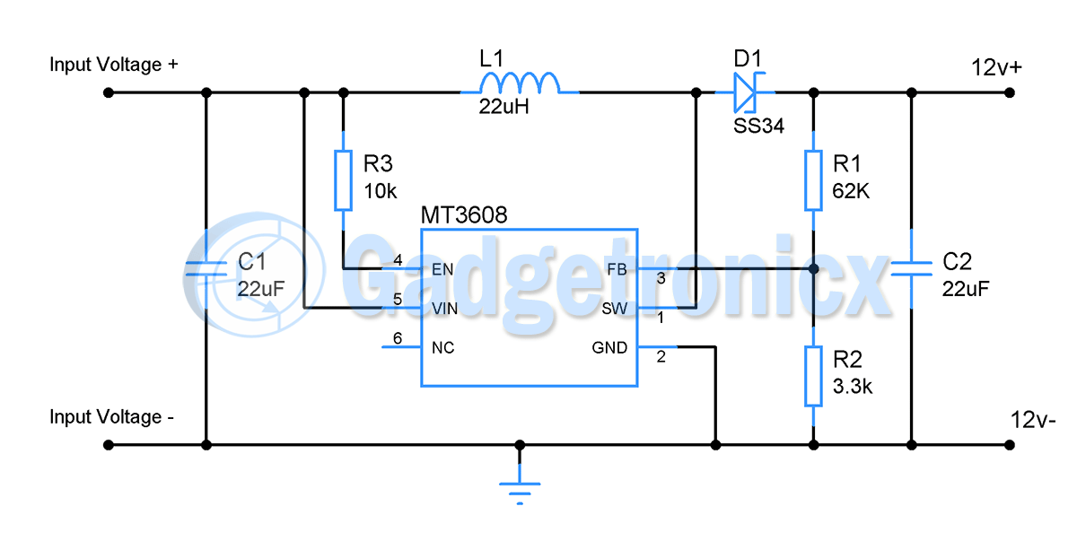
MT3608 2A DC To DC Step Up Power Boost Converter Module. The MT3608 module is a step-up power boost converter, which can regulate the output voltage from 5V to 28V at 1.2Mhz and deliver an output current of a maximum of 2A. The module can be automatically shifted to pulse frequency modulation mode at light loads, and its internal soft-start ...
variable-voltage DC output. A DC-DC switching converter converts voltage directly from DC to DC and is simply known as a DC Converter. A DC converter is equivalent to an AC transformer with a continuously variable turns ratio. It can be used to step down or step up a DC voltage source, as a transformer.

The post explains how to make a high power boost charger circuit which will step up a 12 V DC to any higher level up to 30 V maximum, and at a 3 amp current rate. This high current output can be further enhanced by suitably upgrading the inductor wire gauge specifications. Another great feature of this converter is that the output can be ...
**Introduction** A voltage regulator is a circuit that generates a fixed output voltage of a preset magnitude that remains constant regardless of changes to its input voltage or load conditions. It converts an unstable dc voltage into a stable dc voltage. Its power supply composed of discrete components has the advantages of large output power and wide adaptability. In recent years, integrated regulated power supplies have been widely used. Among them, three-terminal series regulators are the m...

Hey all, thanks in advance for taking the time to look at this question. I'm a mechanical guy by training and electricity is always somewhat mysterious to me, so I'd love to learn more. This question applies to a range of DIY projects that I'd like to work on, and I've been stuck thinking about this for a while. I think this question falls under electronic engineering because ideally I'm looking for responses which can point me in the direction of specific hardware to use (though I don't mind if...

I have gone through and researched lot of DIY UPS projects over youtube and put together these devices. Lot of old spare mobile batteries and 18650s used. Tp5100 and the buck, booster modules are also super cheap to get in the market. Tested both the circuits and i am very happy with the results. Per the circuits, the step-up ( with single li-ion battery will be good for low current consumptions) and the step-down will be enough for raspi 4 current consumptions ( around 2A + ) I elimin...

A couple of weeks ago an amateur put out a call on the local email discussion list. The message was simple, it read: "I have a 606A HP Signal Generator with a copy of the Operating and Service Manual. It covers 50 kHz to 65 MHz. Free to a good home :-)" It's not the first time that such a message has done the rounds, but this time my reply was quick enough for it to be first. Overnight I became the new custodian of a Hewlett Packard 606A Signal Generator. A signal generator is a tool that can ...
A 12V DC to 220 V AC converter can also be designed using simple transistors. It can be used to power lamps up to 35W but can be made to drive more powerful loads by adding more MOSFETS.. The inverter implemented in this circuit is a square wave inverter and works with devices that do not require pure sine wave AC.

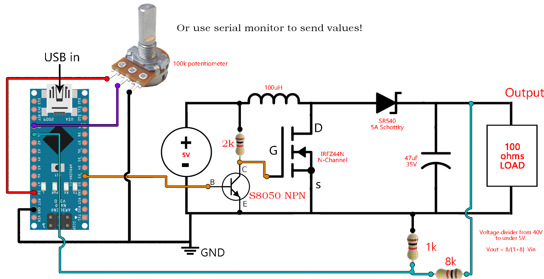
In this project we are going to make a Buck Converter Circuit using Arduino and N-Channel MOSFET with a maximum current capacity of 6 amps. We are going to step down 12v DC to any value between 0 and 10v DC. We can control the output voltage value by rotating the potentiometer. A buck converter is a DC to DC converter, which steps down DC voltage.

Hey Engineers, So I am working on revision 2 of a circuit board for a custom snake tank humidifier and light controller project that I am working on, and I wanted to come to reddit for some feedback on the new iteration before I order the boards. The basic overview of the project is that I have a temp/humidity sensor in each tank, and an arduino that watches that data. When humidity falls below a certain level, the arduino turns on an atomizer in a water reservoir, generating mist, which is the...

Jun 30, 2018 - This is usb 5v to 12v dc-dc step-up converter circuit, or Buck DC to DC converters, it using all transistor so easy to builds

The circuit is divided in to two parts, the first part is a dc to dc step up converter / booster circuit built around a 555 timer ic which boosts the input the second part of the circuit is an adjustable power supply built with lm317 adjustable voltage regulator ic.


0 Response to "42 dc to dc step up converter circuit diagram"
Post a Comment