36 4 wire transmitter wiring diagram
Installation Manual MMI-20027478, Rev AE September 2020 Micro Motion™ 5700 Transmitters with Configurable Inputs and Outputs All Installation Types (Integral, 4-Wire, and 9-Wire)
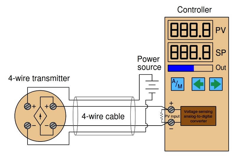
A 4-wire transmitter has 2 wires connected to a power supply and 2 signal wires connected to the PLC. A modulator is used to provide AM voice output from the transmitter. FM Transmitter Circuit Diagram and Working. The published circuit diagrams of Station QRP are for educational purposes only.
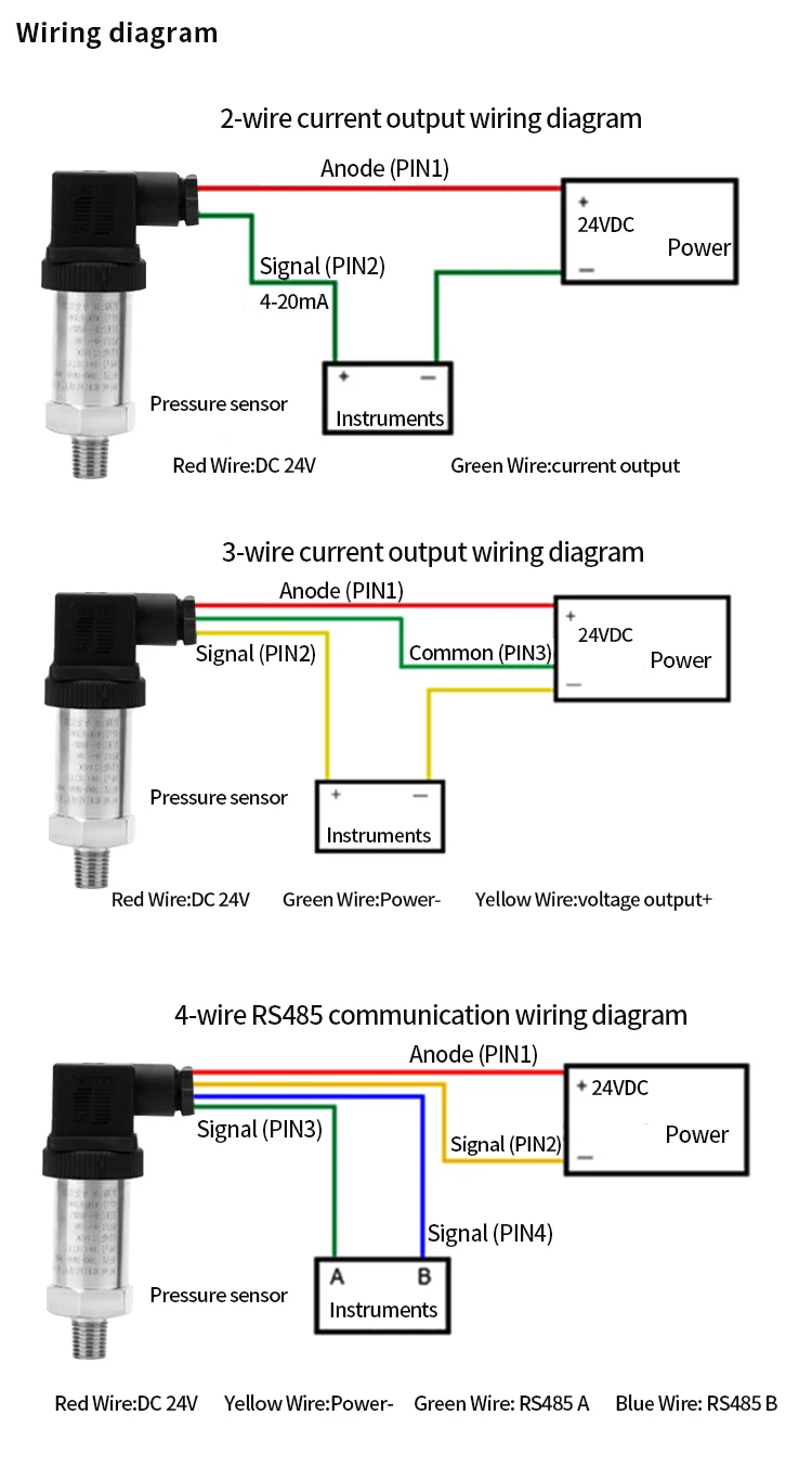
A 4-wire transmitter is usually noted as having a separate power (i.e. plus and minus) supply and an a separate analog output (i.e. plus and minus). I work with all of these all of the time. What I understand you're describing to me is either a 2-wire (4-20 Ma) or a 3-wire voltage transmitter.

4 wire transmitter wiring diagram
2-Wire & 4-Wire Transmitter Wiring Dia gra ms Transmitter 4 - Wire Transmitter 4 - Wire 25 mA Common 25 mA 25 mA Common 25 mA 25 mA Common 25 mA 25 mA Common 7 7 6 5 4 3 2 Output 4-20mA 1 Output 4-20mA 120Vac power ... 4-Wire Transmitter P.O. Box 847 R-Safe Specialty Newman, CA 95360 Tel: 209-862-0230 Toll-free: 1-800-860-3088 Fax: 209-862-0380 ...
4 Wire RTD Wiring Diagram In this circuit there are three leads coming from the RTD instead of two. L1 and L3 carry the measuring current while L2 acts only as a potential lead. No current flows through it while the bridge is in balance.Since L1 and L3 are in separate arms of the bridge,resistance is canceled.
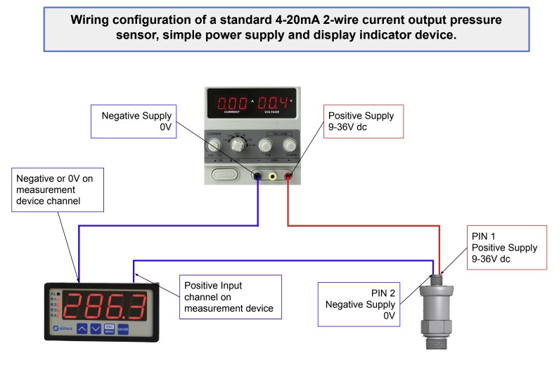
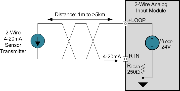
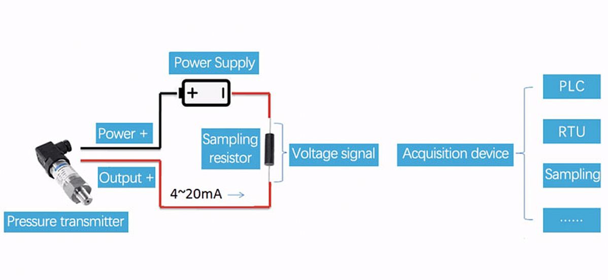
Figure 1. It is a typical usage of two-wire 4-20mA pressure transmitters for most customers showed in figure 1. After the pressure transmitter is powered on, the loop current is proportional to the pressure to generate a 4-20 mA signal by collecting the pressure. The current flow through the sampling resistor (typical 100 Ω, 250 Ω) which ...
4 wire transmitter wiring diagram.
C'mon over to https://realpars.com where you can learn PLC programming faster and easier than you ever thought possible!===== Chec...
7 Loop Powered Signal Isolator Wiring Diagrams Ato Com. Input isolation for 3 wire analog facebook ma transmitter wiring types 2 how to implement a 4 20ma cur loop sensor transmitters loops four output pressure 20 in technology instrumentation questions electrical and nikolay bozov automation 7 powered signal isolator vs ppt connect two entries configurations connections guide 3wire ...
Pt100 Temperature Sensor Wiring Diagram. 3 wire Pt100 RTD Sensor Wiring System. The addition of a third wire, connected to one side of the measuring element, helps to compensate for the lead resistance. It is very important that each of the three wires used in the measuring circuit are equal in terms of both conductor size and length.
3 Wire Pressure Transmitter Wiring Diagram. Pressure transducers installation and wiring diagrams 4 20ma transmitter difference of 20 ma in 2 wire 3 technology wika blog china fst800 1100 25bar 24v 5v dc small low range sensor electrical connections guide dylix corporation 0 5 to vdc 230 psi ss30214g016b4 sendo types no signal from danfoss mbs ...
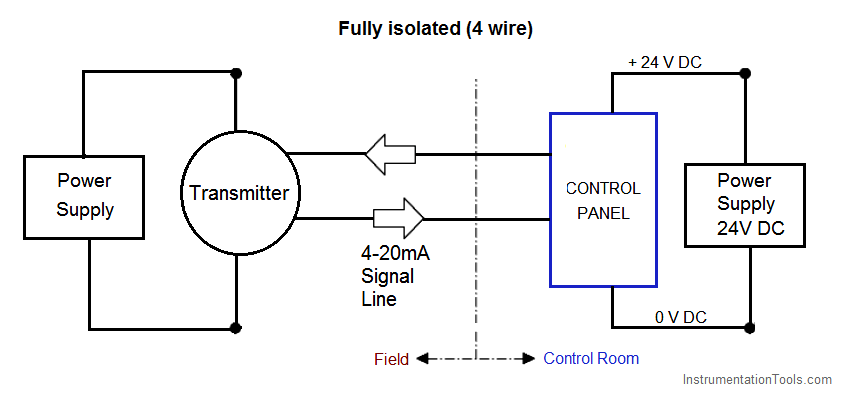
4-wired transmitters here the 4 wires means 2 wires for analog signal (normally 4~20 mA) and 2 wires for pure power supply. 4-wired transmitters need much higher working voltage and working current to satisfy the device functionality (compare with 2-wired loop powered transmitters).
In a 4-20mA loop, 4mA represents the low end of the measurement range and 20mA represents the high end. The voltage specification for most transmitters comes in a range. For example if the voltage of a 2 - wire transmitter is specified as 15 to 24VDC, the lower voltage is the minimum voltage necessary to guarantee proper transmitter operation.
4-wire sensor transmitter simplified block diagram Unlike the 2- and 3-wire transmitter representations shown in Figure 2, the 4-wire circuit has separate paths for the power current and signal current. Also, the 4-wire receiver does not share a common return (GND) with the power supply.
Pressure transducers installation and wiring diagrams 4 20ma transmitter 3 wire electrical connections guide dylix corporation difference of 20 ma in 2 technology wika blog types china fst800 1100 25bar 24v 5v dc small low range sensor voltage output transducer comparison te connectivity how to add a coolant avoid rookie mistake autosport labs 0 40 mpa 5 volt… Read More »
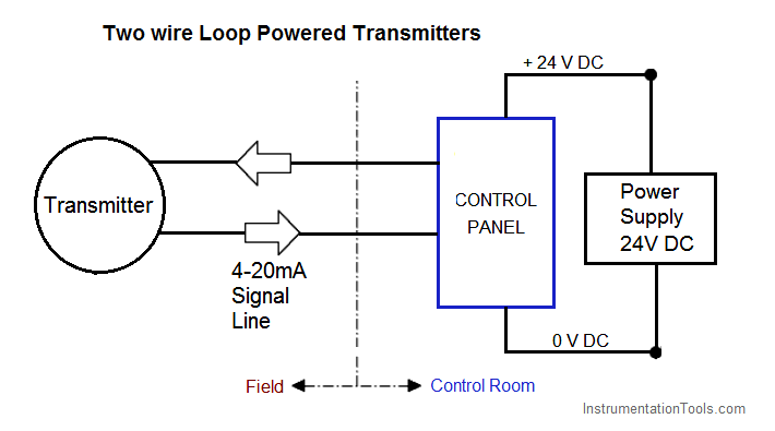
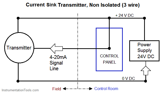
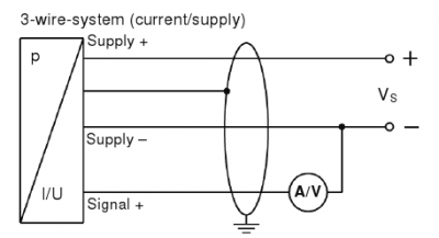
4-20 mA Transmitter Wiring. Several transmitter wiring options exist. The design of the associated control panel dictates which option should be used. These wiring options include: Current source transmitter, non isolated (3 wire) Current sink transmitter, non isolated (3 wire) Fully isolated (4 wire) Two wire loop powered transmitters
Tel 248-295-0880 Fax 248-624-9234 sales@acromag.com www.acromag.com 30765 Wixom Rd, Wixom, MI 48393 USA INTRODUCTION TO THE TWO-WIRE TRANSMITTER AND THE 4-20MA CURRENT LOOP 6 3. Transmitter: This is the device used to transmit data from a sensor over the two-wire current loop. There can be only one Transmitter output in any
The system is called balanced, because the signal on one wire is ideally the exact opposite of the signal on the second wire. In other words, if one wire is transmitting a high, the other wire will be transmitting a low, and vice versa. See Figure 2. Figure 2. The signals on the 2 wires of a balanced system are ideally opposite.
May 25, 2020 · – The actual wiring between the transmitter and the power supply depends upon whether it is a 2-wire or a 4-wire type. – A 4-wire transmitter has 2 wires connected to a power supply, and 2 signal wires connected to the PLC. – A 2-wire transmitter has only 2 wires and is connected in series with the power supply and the PLC.
A 4 wire transmitter has 2 wires connected to a power supply and 2 signal wires connected to the plc. For complete instructions on wiring a basic 4 way switch see our wiring a 4 way switch article. To view it at full size click on the diagram. In this circuit there are three leads coming from the rtd instead of two.
Nov 19, 2021 · 4 Wire Transmitter Wiring Diagram. November 19, 2021 by Larry A. Wellborn. Assortment of 4 wire transmitter wiring diagram. A wiring diagram is a streamlined standard photographic representation of an electrical circuit. It shows the components of the circuit as streamlined shapes, and also the power as well as signal links between the tools.
Practical diagrams. 4 - 20 mA loops are built from in series connected elements. Shielded twisted pair wiring is often used to connect the longest distance between the field transmitter and remote receiver. The receiver device is commonly the input channel of a Programmable Logic Controller (PLC), a Digital Control System (DCS), or a panel meter.
It reveals the parts of the circuit as streamlined shapes and the power as well as signal connections in between the gadgets. A 4 wire transmitter has 2 wires connected to a power supply and 2 signal wires connected to the plc. Variety of 2 wire pressure transducer wiring diagram. Wiring diagram pics detail.
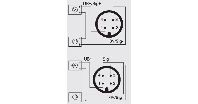
2-wire. 3-wire. UB. 1. 1. 0V. 2 Connection diagrams. All connectors with .The model S pressure transmitter for general industrial applications is the ideal solution for customers with demanding measuring requirements. It features a very good accuracy, a robust design and an exceptional number of variants, meaning it can be suited to the widest ...
A DC common wire is run from the instrument to the transmitter. This permits the transmitter to draw whatever power it needs from the power supply and produce the desired signal current at the transmitter output. The schematic diagram for a 3 -wire transmitter is shown below:
What is 4 wire transmitter? 4 wire transmitter wiring diagram. The figure above shows the wiring diagram of the four-wire transmitter. Most of the power supply is AC 220V, and some are DC 24V. DC4 ~ 20 ma output signals and the load resistance is 250 Ω, or DC0-10 ma, load resistance to 0-1.5 K Ω; Some also have mA and mV signals, but the load resistance or input resistance, depending on the output circuit form and different values. What is 3 wire transmitter? 3 wire transmitter wiring diagram
Temperature transmitter txblock usb wilkerson instrument company inc blog rtd two wire transmitters and how they work wiring diagrams resistance detector working types 2 3 4 what is an useore by jms southeast universal controllers difference between s sensor a probe rosemount 248 reference manual pt100 pinout features uses guide datasheet simple realization of fully integrated measurement ...
The 2-wire transmitter is just an additional to the card. If you have traditional AI card with a 4-wire term block, it can also do 2-wire transmitters. Refer to Books On Line (BOL) for your version of DeltaV and IO type for additional information. The Terminal Block mentioned applies only to S-Series (AI Card has 2 Wire and 4 Wire in a Single ...
2 wire for current transducers and 3 wire for voltage transducers. 4 wire pressure transducer wiring diagram. Next disconnect the wire form the transducer that is connected to the control circuit and place the lead form the digital milliamp meter to the black wire. Here are links to the user manuals for the sensors. Posted by tracy molnar on tue.
8. Install field wiring conduit into the open transmitter conduit entry (for remote mounting) and feed wires into the transmitter housing. 9. Pull the field wiring leads into the terminal side of the housing. 10. Attach the sensor leads to the transmitter sensor terminals. The wiring diagram is located inside the housing cover. 11.

4-20 ma transmitter wiring: 4wire transmitter connection & 2wire loop powered transmitter connection










0 Response to "36 4 wire transmitter wiring diagram"
Post a Comment