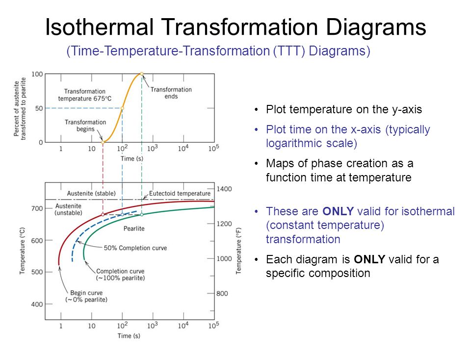
42 isothermal transformation diagram for an iron–carbon alloy
Isothermal transformation diagrams university of portland isothermal transformation diagrams 10 18 using the isothermal transformation diagram for an ironcarbon alloy of eutectoid position download free and get a copy in your email. 1019 using the isothermal transformation diagram for an iron carbon alloy of eutectoid composition figure 1022 specify the nature of the final microstructure in ... Transcribed image text: Using the isothermal transformation diagram for an iron-carbon alloy of eutectoid composition (Fe-0.76 wt%C), specify the final ...
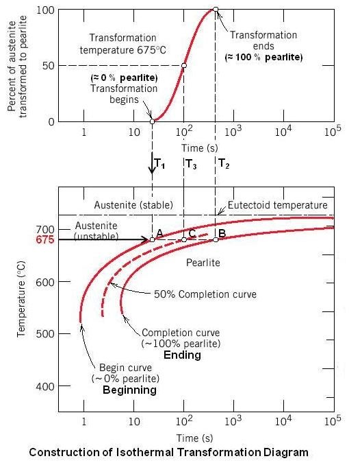
Step 1. 1 of 3. We have to use the isothermal transformation diagram for an iron-carbon alloy of eutectoid composition form Figure 10.22 in order to specify the nature of the final microstructure of a small specimen: T 1 = 760 C T_1=760\text { C} T 1 = 760 C. A) \textbf { A)} A) Cool rapidly to. T = 350 C T=350\text { C} T = 350 C.
Isothermal transformation diagram for an iron–carbon alloy
29 May 2017 — Solutions of some problems of chapter 10 Phase transformations in book ... the isothermal transformation diagram for an iron–carbon alloy of ... Using the isothermal transformation diagram for an iron-carbon alloy of eutectoid composition (see Figure 10.22 below), specify the nature of the final ... Using the isothermal transformation diagram for an iron-carbon alloy of eutectoid composition (Figure below), specify the nature of the final microstructure (in terms of micro-constituents present and approximate percentages of each) of a small specimen that has been subjected to the following time-temperature treatment: Rapidly cool to 625oC, hold for 10 s, then quench to room temperature.
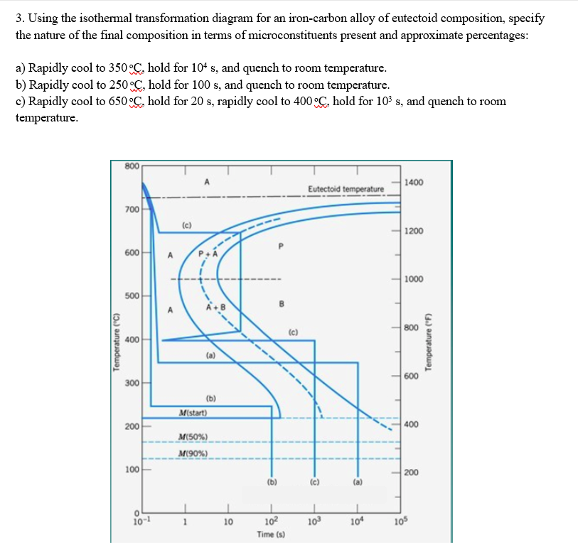
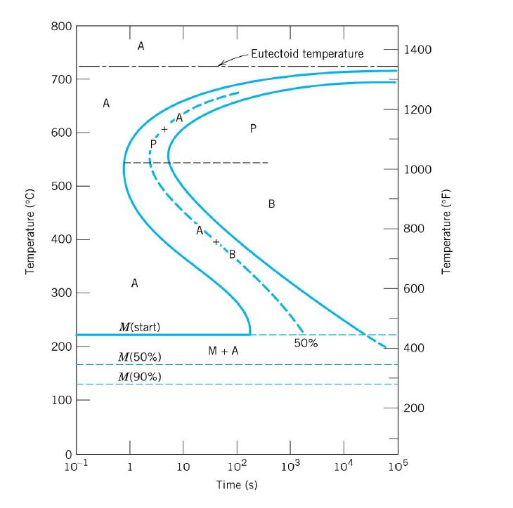
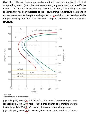
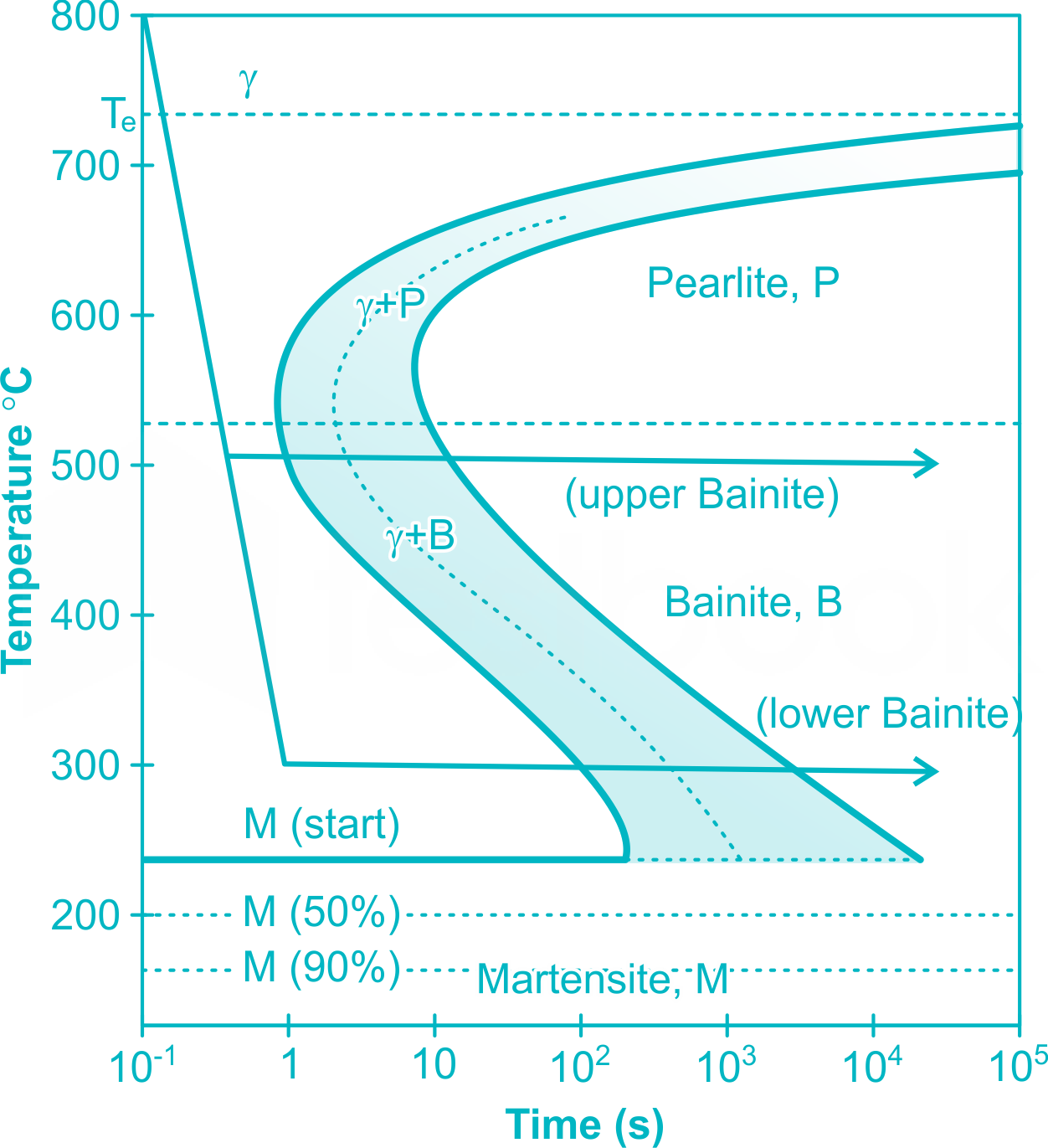
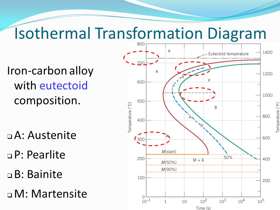
Isothermal transformation diagram for an iron–carbon alloy. Isothermal transformation diagram for an iron-carbon alloy of eutectoid composition, including austenite-to-pearlite (A–P) and austenite-to-bainite (A–B) transformations. “Nose” of T-T-T curve between pearlite and bainite transformations means bainite cannot be We are called upon to consider the isothermal transformation of an iron-carbon alloy of eutectoid composition. (a) From Figure 10.22, a horizontal line at 550°C ...12 pages Transcribed image text: (1) Given: Isothermal transformation diagram for an iron-carbon alloy of eutectoid composition (Fig. 10.22). 7.3. Using the isothermal transformation diagram for an iron–carbon alloy of eutectoid composition, specify the nature of the final microstructure of a small specimen that has been subjected to the following time–temperature treatments. In each case assume that the specimen begins at 760°C and that it has been held at this temperature long ...
10.18 Using the isothermal transformation diagram for an iron–carbon alloy of eutectoid composition (Figure 10.22), specify the nature of the final microstructure (in terms of microconstituents present and approximate percentages of each) of a small specimen that has been subjected to the following time–temperature treatments. In 1019 using the isothermal transformation diagram for an iron carbon alloy of eutectoid composition. The thickness of the ferrite and cementite layers in pearlite is 81. Figure 1022 specify the nature of the final microstructure in terms of microconstituents present and. 6 Make A Copy Of The Isothermal Transformation Diagram For An Iron Transcribed image text: The TTT (isothermal transformation) diagram for an iron-carbon alloy with 1.13 wt. % C is shown below. Sketch and label the ... 5. Using the isothermal transformation diagram for an iron-carbon alloy of eutectoid composition (Figure 10.23), specify the nature of the final microstructure (in terms of microconstituents presentand approximate percentages of each) of a small specimen that has been subjected to the following time-temperature treatments.
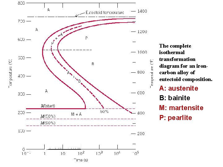
Using the isothermal transformation diagram for an iron–carbon alloy of eutectoid composition (Figure 10.23), specify the nature of the final microstructure (in terms of microconstituents presentand approximate percentages of each) of a small specimen that has been subjected to the following time –temperature treatments. In each case assume ... Transcribed image text: 9. With the isothermal transformation diagram for an iron-carbon alloy of eutectoid composition (Figure below) and then sketch and label time-temperature paths on this diagram to produce the following microstructures: (a) 100% upper bainite (b) 100% fine pearlite (c) 50% coarse pearlite, and 50% martensite (d) 50% fine pearlite, 25% upper bainite and 25% martensite TTT ... The complete isothermal transformation diagram for an iron- carbon alloy of eutectoid composition. A: austenite. B: bainite. M: martensite. P: pearlite ...46 pages Two limitations of the iron-iron carbide phase diagram are: ... 10.18 Using the isothermal transformation diagram for an iron–carbon alloy of eutectoid ...27 pages
Faculty Up Edu
Using the isothermal transformation diagram for an iron-carbon alloy of eutectoid composition (Figure below), specify the nature of the final microstructure (in terms of micro-constituents present and approximate percentages of each) of a small specimen that has been subjected to the following time-temperature treatment: Rapidly cool to 625oC, hold for 10 s, then quench to room temperature.
Answered Using The Isothermal Transformation Bartleby
Using the isothermal transformation diagram for an iron-carbon alloy of eutectoid composition (see Figure 10.22 below), specify the nature of the final ...

Using The Isothermal Transformation Diagram For An Iron Carbon Alloy Of Eutectoid Composition Specify The Nature Of The Final Microstructure In Terms Of Microconstituents Present And Approximate Perc Study Com
29 May 2017 — Solutions of some problems of chapter 10 Phase transformations in book ... the isothermal transformation diagram for an iron–carbon alloy of ...

Using The Isothermal Transformation Diagram For A 0 45 Wt Csteel Alloy Figure Below From Callister Rethwisch Homeworklib
Uobabylon Edu Iq

Roop Lal Asst Prof Pdf Free Download
Solved Using The Isothermal Transformation Diagram For An Chegg Com

Below Is Shown The Isothermal Transformation Diagram For A 0 45 Wt C Iron Carbon Alloy List The Microconstituent S Present For The Heat Treatment Labeled A On This Diagram It Is Not Necessary To
Answered Using The Isothermal Transformation Bartleby

Problem 3 20 Pts Using The Phase Diagram And Isothermal Transformation Diagram For An Iron Carbon Alloy Of Eutectoid Composition Assuming That The Specimen Begins At 760 C And That It Has Homeworklib
Examples Of Iron Iron Carbide Transformations
Pdfcoffee Com
Faculty Up Edu
Uobabylon Edu Iq
Staff Emu Edu Tr

Using The Isothermal Transformation Diagram For An Alloy Steel Type 4340 Specify The Nature Of The Final Microstruct Homeworklib
Time Temperature Transformation Ttt Curve Mcq Free Pdf Objective Question Answer For Time Temperature Transformation Ttt Curve Quiz Download Now

Ttt Diagram Of Steel In Material Science Materials Today

Isothermal Transformation Behavior And Microstructural Evolution Of Micro Alloyed Steel Intechopen
Che Uri Edu
Xdocs Tips

Solved 2 Given Isothermal Transformation Diagram For A Chegg Com

Using The Isothermal Transformation Diagram For An Iron Carbon Alloy Of Course Hero
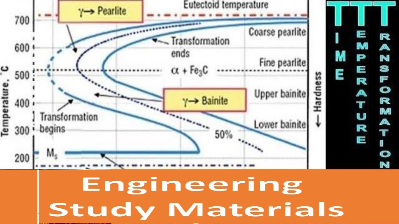
Ttt Diagram Explained Time Temperature Transformation Diagram Curves Engineering Study Materials Youtube
Practical Maintenance Blog Archive I T Diagram And Cooling Curves
Module 5 Metallic Materials Http Www Tntech Edumecourseszhangmodule205m
Afendirojan Files Wordpress Com
Isothermal Transformation Diagrams Ppt Video Online Download

Isothermal Transformation Diagram Wikipedia
Phase Transformations In Metals Ppt Download

Using The Isothermal Transformation Diagram For A 1 13 Wt Percent C Steel Alloy Determine The Final Microstructure In Terms Of Just The Microconstituents Present Of A Small Specimen That Has Been Subjected

Sparky S Sword Science Alloys Microstructures And Phase Diagrams

Using The Isothermal Transformation Diagram For An Iron Carbon Alloy Of Eutectoid Composition Specify The Nature Of The Final Microstructure Of A Small Specimen That Has Been Subjected To The Following Time Temperature Treatments
Pdfcoffee Com

An Isothermal Transformation Diagram For A Medium Carbon Steel With The Download Scientific Diagram
Iron Phase Diagram Roy Mech

Isothermal Transformation Diagram Wikipedia

Using The Isothermal Transformation Diagram For An Iron Carbon Alloy Of Eutectoid Composition Figure 11 23 Specify The Nature Of The Final Microstructure In Terms Of Microconstituents Present And Study Com

Oneclass Using The Supplied Isothermal Transformation Diagram For An Irona Carbon Alloy Of Eutectoi
(171).jpg)
Ttt Time Temperature Transformation Diagram Quiz Proprofs Quiz

Ttt Diagram Basic Ttt Diagram For Steel Eutectoid Steel

The Combining Effects Of Ausforming And Below Ms Or Above Ms Austempering On The Transformation Kinetics Microstructure And Mechanical Properties Of Low Carbon Bainitic Steel Sciencedirect
0 Response to "42 isothermal transformation diagram for an iron–carbon alloy"
Post a Comment