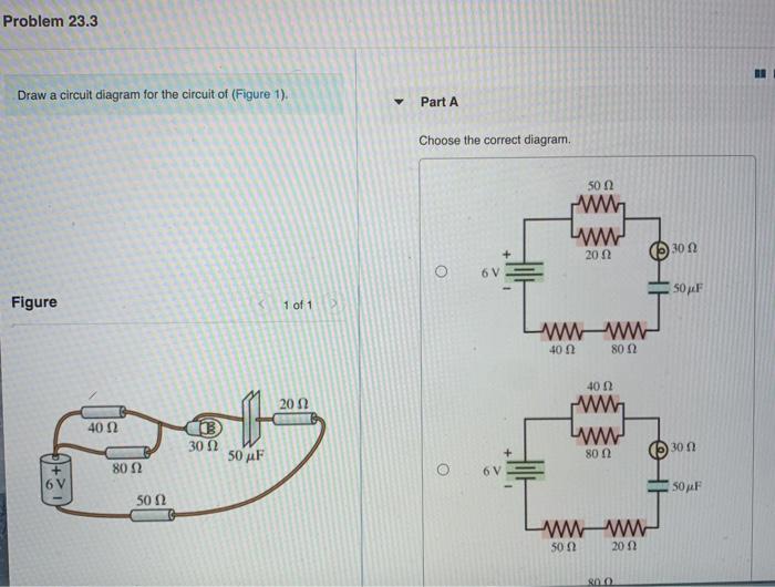
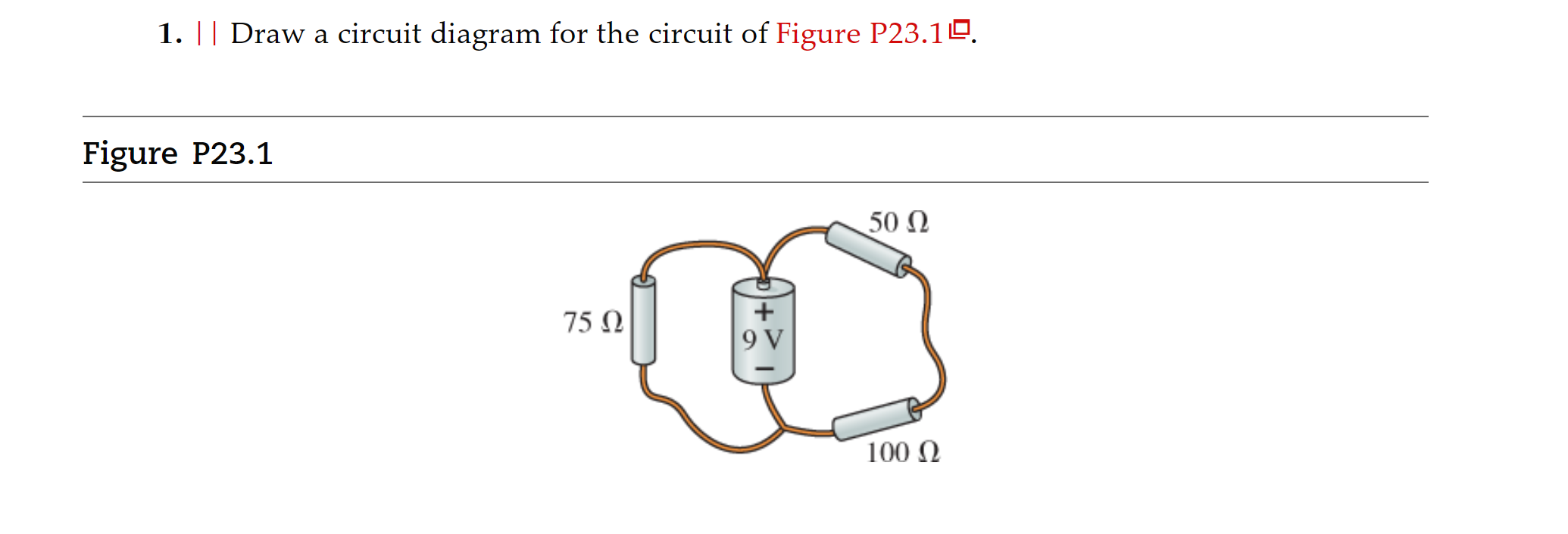
39 draw a circuit diagram for the circuit of (figure 1).
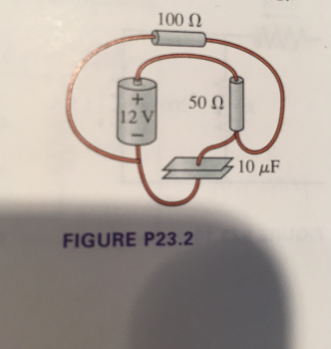
1 Draw the circuit diagram in Figure 2a on your Circuit Wizard software Make from BTTE 819 at Surigao State College of Technology - Surigao City Draw a circuit diagram for the circuit of (Figure 1). You may want to review (Page 728) . 1 of 1A circuit is shown in the figure. A 12-volt battery is connected by wires to two resistors and a capacitor. The positive terminal of the battery is connected to a 50-ohm resistor, and the negative terminal of the battery is connected to one terminal ...
To draw a circuit diagram from a complex circuit follow the steps as: 1.Start with a collection of electrical symbols appropriate for diagram. 2.Draw circuits represented by lines from the complex given circuit. 3.Drag and drop symbols to the circuits as per the components given in the circuit and connect them appropriately.

Draw a circuit diagram for the circuit of (figure 1).
7.1 Consider the timing diagram in Figure P7.1. Assuming that the D and Clock inputs shown are applied to the circuit in Figure 7.12, draw the waveforms for the Qa, Qb, Qc signals. 7.5 Given a 100-MHz clock signal, derive a circuit using D FF to generate 50-MHz and 25-MHz clock signals. Draw a timing diagram for all three clock signals, assuming This preview shows page 1 - 3 out of 3 pages. View full document. Question: Determine Vo1 and Vo2 for the networks of Fig. FIG. Answer : (a) Draw the circuit diagram: Figure 1. The silicon (Si) diode voltage is 0.7 V The silicon diode is forward biased and is in the ON state. Apply Kirchhoff’s voltage law for loop 1, to obtain the Hence ... Draw a circuit diagram for the circuit of figure 1. A single cell or other power source is represented by a long and a short parallel line. The circuit could be more complicated if the student understands the concepts. 13 draw the circuit from figure 1 the components from figure 1 are found in the following locations.
Draw a circuit diagram for the circuit of (figure 1).. Figure 2—Circuit drawing Line diagram: a one-line diagram or single-line diagram is a simplified notation for representing an electrical system. The one-line diagram is similar to a block diagram except that electrical elements such as switches, circuit breakers, transformers, and capacitors are shown by However, the safety pin is not connected with one of the drawing pins. Thus, the circuit is not complete. Hence, safety pin represents a switch in 'OFF' position. The circuit diagram of the given figure is shown in the following figure Draw a circuit diagram of the circuit in Figure 4 in the space to the right of it. Figure 4: Three cells in parallel connected to a lamp When cells are connected in parallel, the total voltage of the cells is the same as that of a single cell (1,5 volts). Parameters: circuit (QuantumCircuit) - the quantum circuit to draw; scale (float) - scale of image to draw (shrink if < 1); filename (str) - file path to save image to; style (dict or str) - dictionary of style or file name of style file.This option is only used by the mpl, latex, and latex_source output types. If a str is passed in that is the path to a json file which contains that ...
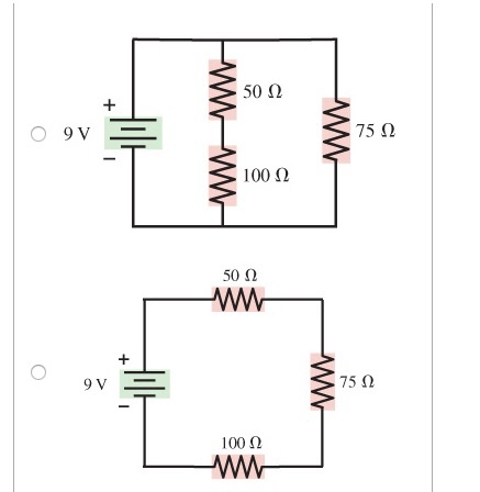
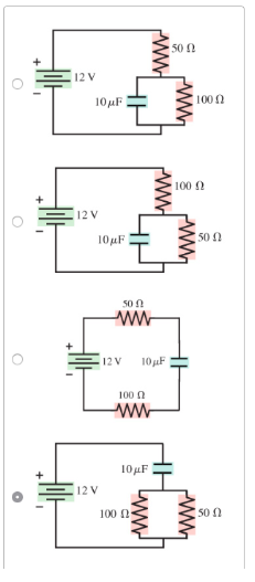
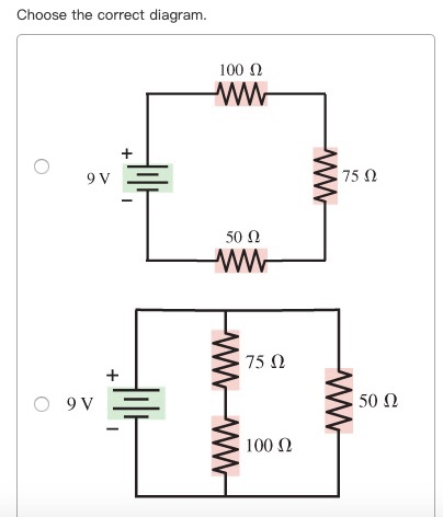
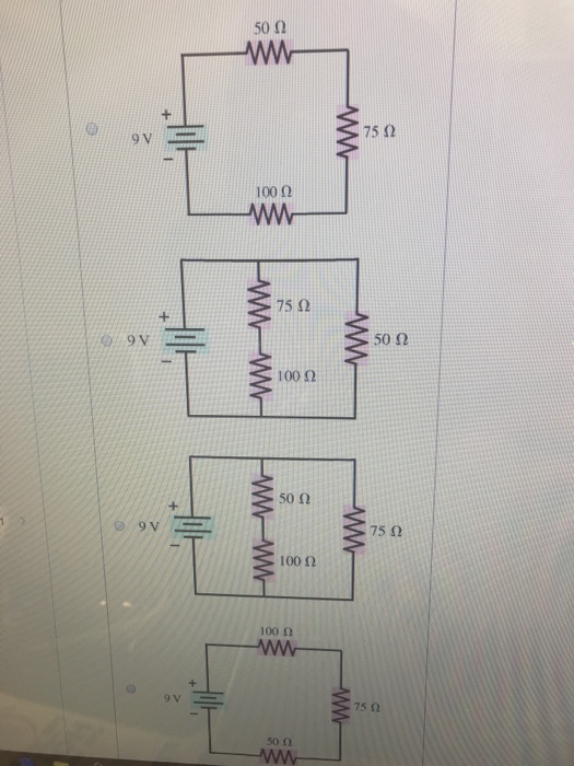
Science; Advanced Physics; Advanced Physics questions and answers; Draw a circuit diagram for the circuit of (Figure 1). Choose the correct diagram. 10μF 12 V 50 Ω 100 50 0 10μF 12 V 100 ww 50 12 V Figure 1 of 1 100 Ω 10μF 100 100 + 50 12 V 12 V 50 10 μF 10μF WW wwW + + According to the circuit board to draw the circuit schematic is also a method and skill, the key is to be familiar with the common circuit of various components, so drawing is easier. 1. Method of drawing a triode amplifier circuit. 1) The first step is to draw the three-level tube circuit graphic symbol first. (i) Draw a circuit diagram to study the input and output characteristics of an n-p-n transistor in its common emitter configuration. Draw the typical input and output characteristics. (ii) Explain, with the help of a circuit diagram, the working of n-p-n transistor as a common emitter amplifier. Circuit Diagram is a free application for making electronic circuit diagrams and exporting them as images. Design circuits online in your browser or using the desktop application.
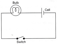
The circuit diagram to represent the circuit shown in figure can be drawn as mentioned above in the fig. Answer verified by Toppr. 174 Views. Figure 2.1 A basic four-bit shift register can be constructed using four D flip-flops, as shown in Figure 2.1. The operation of the circuit is as follows. ?? The register is first cleared, forcing all four outputs to zero. ?? The input data is then applied sequentially to the D input of the first flip-flop on the left (FF0). It is a simple circuit as shown here. on the left is a picture of what it looks like in real life, and on the right is a simplified diagram: Figure 1. A simple circuit diagram. There are a few things to notice her e in the circuit diagram - the wires connecting the cell and a bulb are all at 90 0, making a rectangular shape. This is to make the ... On the edge of the printing plate, at least every 5 inches for a certain support. The factors that must be considered when selecting and designing printed circuit boards are as follows: 1) The size and shape of the printed circuit board. 2) The type of mechanical accessories and plug (seat) required. 3) The environmental adaptability of circuits.
Solved A Review Constants Periodic Ta Draw A Circuit Diagram Chegg Com
Explanation. Step 1. 1 of 2. The circuit diagram of the basic inverting amplifier configuration is shown in figure below. Expression for the closed-loop voltage gain. A v A_v A v . if the circuit is: A v = v o v i n A_v=\frac {v_o} {v_ {in}} A v = v in v o . Input voltage.
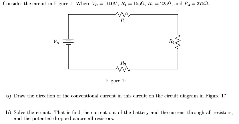
Solved Consider The Circuit In Figure 1 Where Vb 10 0v Ri 15502 R2 22502 And Rx 37502 Figure 1 Draw The Direction Of The Conventional Current In This Circuit On The Circuit
The construction of Circuit diagrams 6.0 Tutor Marked Assignment 1) In the figure below, change each AND gate to an OR gate, and change the OR gate to an AND gate. Then write the expression for output x. 2) Draw a logic circuit for the function F = (A + B)(B + C)(A + C), using NAND gates only. 3) Draw the circuit diagram for the expression x ...

Time Constant Calculations Worksheet Dc Electric Circuits
You can try some of these exercises which covers the analysis and design of sequential circuits. Analysis of Sequential Circuits. 1. Derive a) excitation equations, b) next state equations, c) a state/output table, and d) a state diagram for the circuit shown in Figure 1.1. Draw the timing diagram of the circuit.
3
Using axglyph draw high quality circuit diagram step1. Download axglyph and install it with a word add in. Draw a circuit diagram for the circuit of figure 1. Press r to rotate part after double clicking it to choose it from the place parts window before placing it into the project press w to. Analog library called r l.
Circuit Diagram Maker Free Online App
1. Edraw Max. Edraw Max can be considered a great software and one of the best circuit diagram makers in 2021 as it is freely available to people to build and design neat-looking and illustratively impacting diagrammed designs. Edraw Max. It can be easily logged on to through a web browser in Windows, Mac and the Linux platform.

Circuit Diagram Maker Lucidchart
Q 1. Draw a circuit diagram to represent the circuit shown in figure. Q 2. Draw circuit diagram of common base configuration. Q 3. Draw the circuit diagram of a full wave rectifier and state how it works . Q 4. Draw a circuit diagram to show how a soft iron piece can be transformed into an electromagnet.
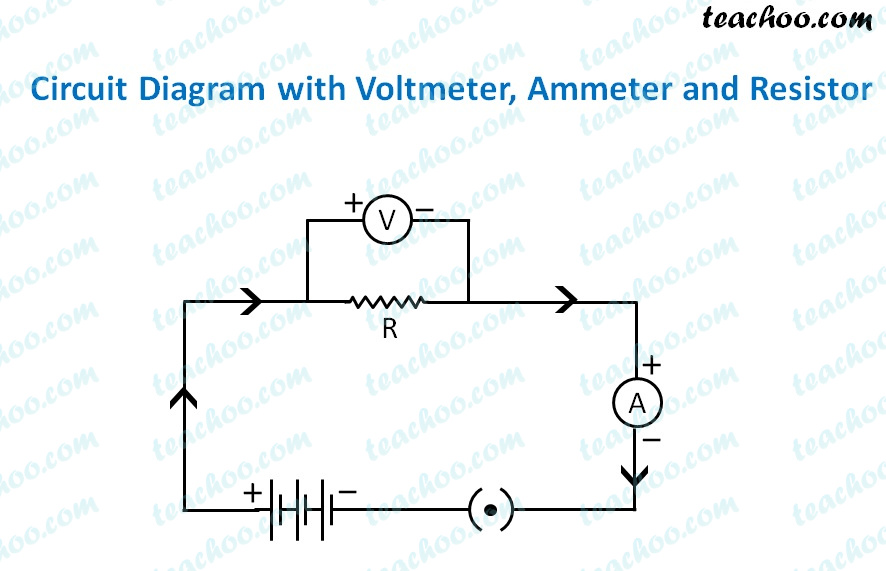
Electric Circuit Diagram Symbol Open And Closed Circuit Teachoo
(a) Draw the circuit diagram for studying the characteristics of a transistor in common emitter configuration. Explain briefly and show how input and output characteristics are drawn. (b) The figure shows input waveforms A and B to a logic gate. Draw the output waveform for an OR gate.
Solved Draw A Circuit Diagram For The Circuit Of Figure 1 Chegg Com
Experts are tested by Chegg as specialists in their subject area. We review their content and use your feedback to keep the quality high. Transcribed image text: Draw a circuit diagram for the circuit of (Figure 1).

Circuit Diagram For Tcd Download Scientific Diagram
Solution: In the given circuit, one end of the bulb is connected with one end of the cell while their other terminals are connected to a safety pin. However, the safety pin is not connected with one of the drawing pins. Thus, the circuit is not complete. Hence, the safety pin represents a switch in the ‘OFF’ position. Set your child up for ...
Solved Draw A Circuit Diagram For The Circuit Of Figure Chegg Com
Draw a circuit diagram for the circuit of figure 1. Draw a circuit diagram for the circuit of figure 1. Xcircuit is one of the widely used software for drawing publishing quality circuit diagrams. Now wire up the circuit from figure 11 battery bulb and switch all connected with clip on wires switch closed bulb on.

Draw The Circuit Diagram To Represent The Circuit Shown In Figure Science Shaalaa Com
1-408-294-8324 thetech.org This activity is meant to extend your students' knowledge of the topics covered in our Simplicity of Electricity lab. In this activity, students will learn how to draw circuit diagrams and figure out if their circuit diagram will produce a working circuit. Grade Levels: 4-8 Estimated Time: 45 minutes Student ...

Physics Reference The Circuit Diagram Of Fig 9 1 Is An Amplifier Circuit Incorporating An Operational Amplifier Op Amp
This video provides a very easy concept of drawing phasor diagram for any complex network. concept of drawing phasor diagram for series and parallel R-L-C Ci...

Q1 Page 213 Draw A Schematic Diagram Of A Circuit Consisting
This problem has been solved! See the answer. Draw a circuit diagram for the circuit of (Figure 1) . Choose the correct diagram:

Q2 Draw The Circuit Diagram To Lido
Download the Notes TOPIC 1: Logic Representation There are three common ways in which to represent logic. 1. Truth Tables 2. Logic Circuit Diagram 3. Boolean Expression We will discuss each herein and demonstrate ways to convert between them. TOPIC 2: Truth Tables A truth table is a chart of 1s and 0s arranged to…

Basic Pneumatic Circuits Tech Briefs
We've seen the Symbols of the Most Common Electrical Components that are used to represent them. In this video, we will look at how to draw Circuit Diagrams ...

Chopper Dc To Dc Converter Electrical4u
Draw a circuit diagram for the circuit of figure 1. A single cell or other power source is represented by a long and a short parallel line. The circuit could be more complicated if the student understands the concepts. 13 draw the circuit from figure 1 the components from figure 1 are found in the following locations.

48v Backplane Impedance Analyzer Takes The Guesswork Out Of Sizing Clippers And Snubbers Analog Devices
This preview shows page 1 - 3 out of 3 pages. View full document. Question: Determine Vo1 and Vo2 for the networks of Fig. FIG. Answer : (a) Draw the circuit diagram: Figure 1. The silicon (Si) diode voltage is 0.7 V The silicon diode is forward biased and is in the ON state. Apply Kirchhoff’s voltage law for loop 1, to obtain the Hence ...
Solved Determine The Current I For Each Of The Congurations Of Fig 155 Using The Approximate Equivalent Model For The Diode B Fig 155 Problem 5 Course Hero
7.1 Consider the timing diagram in Figure P7.1. Assuming that the D and Clock inputs shown are applied to the circuit in Figure 7.12, draw the waveforms for the Qa, Qb, Qc signals. 7.5 Given a 100-MHz clock signal, derive a circuit using D FF to generate 50-MHz and 25-MHz clock signals. Draw a timing diagram for all three clock signals, assuming

Draw A Circuit Diagram For The Circuit Of Figure 1 You May Want To Review Page Homeworklib

Dc Voltmeters And Ammeters Physics
Draw The Circuit Diagram For The Circuit O Clutch Prep
Solved Lamun Problem 23 3 Draw A Circuit Diagram For The Chegg Com

Accurate Fuel Gauging Through State Of Charge Measurement Bench
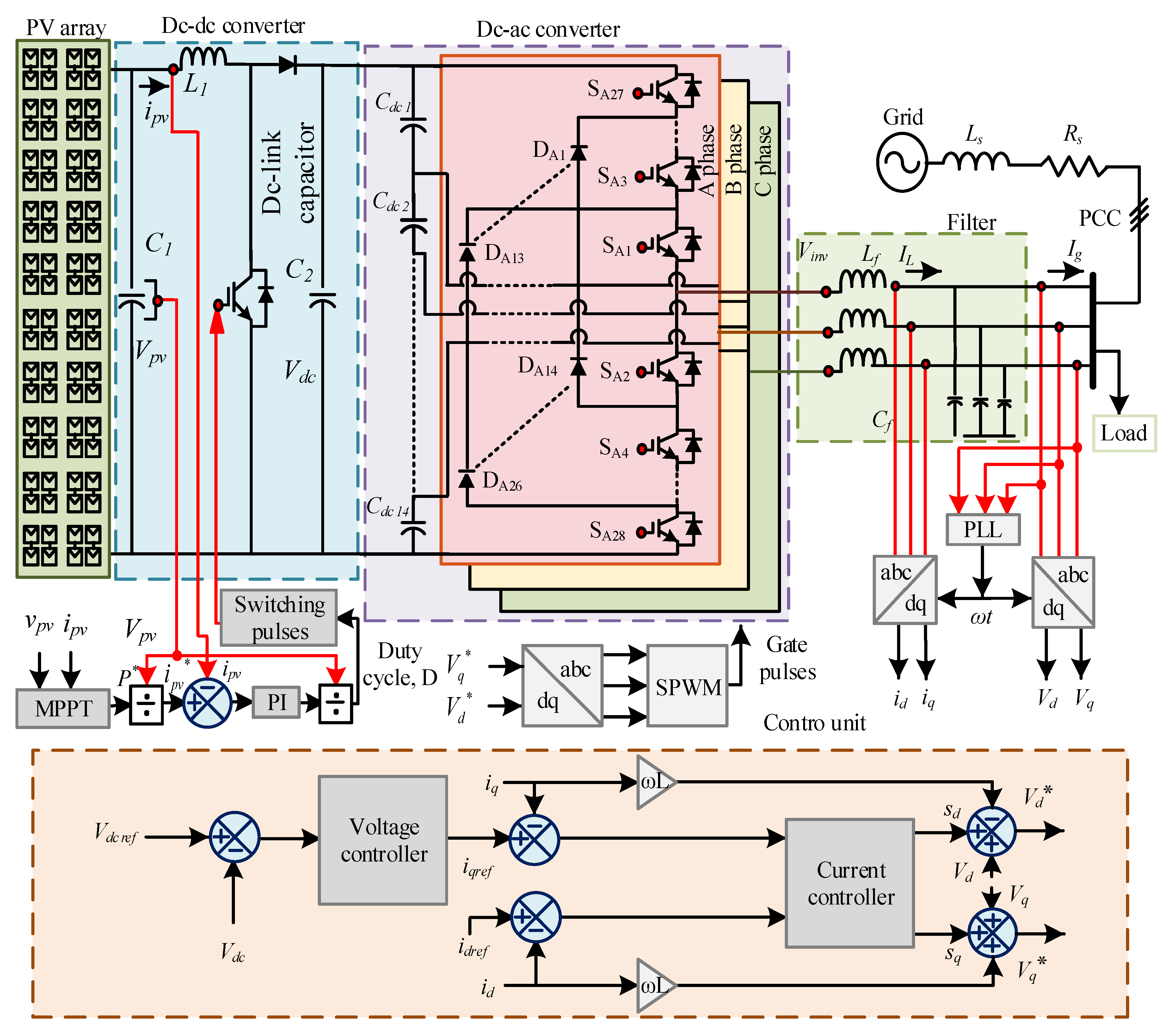
Sustainability Free Full Text An Advanced Control Technique For Power Quality Improvement Of Grid Tied Multilevel Inverter
Solved Draw A Circuit Diagram For The Circuit Of Figure 1 Chegg Com
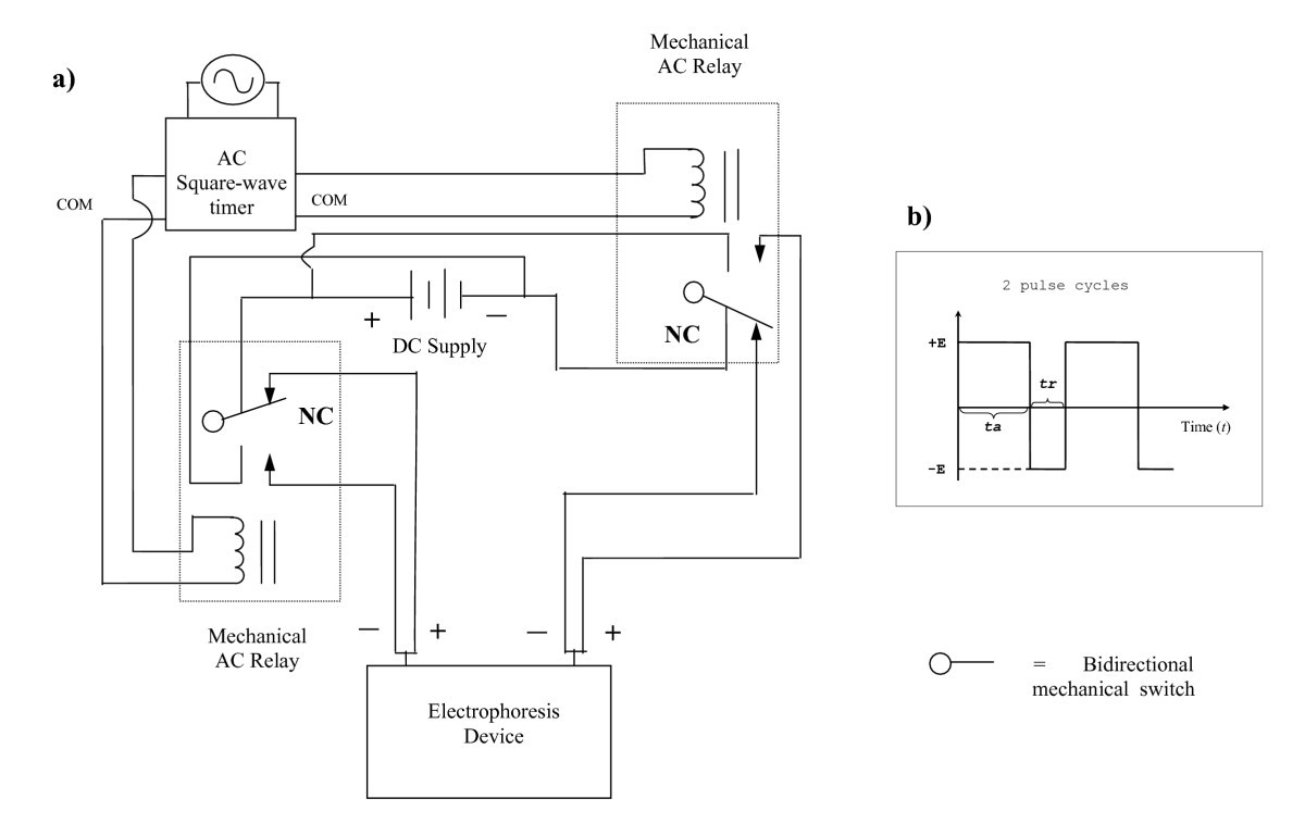
Increase In Local Protein Concentration By Field Inversion Gel Electrophoresis Proteome Science Full Text

Circuit Diagram For Temperature Measurement And Control System Download Scientific Diagram
Draw The Circuit Diagram To Represent The Circuit Shown Below Studyrankersonline
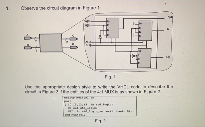
Solved 1 Observe The Circuit Diagram In Figure 1 A O B O Chegg Com
2
Solved 1 Draw A Circuit Diagram For The Circuit Of Chegg Com

Q2 Draw The Circuit Diagram To Lido
Solved Draw A Circuit Diagram For The Circuit Of Figure P23 1
Circuit
Solved Draw A Circuit Diagram For The Circuit Of Figure 1 Chegg Com

Solved Draw A Circuit Diagram For The Circuit Of Figure 1 Chegg Com
1
Carefully Study The Circuit Diagram In Figure And Calculate The Value Of Resistor X Sarthaks Econnect Largest Online Education Community

Mode 2 Operation Schematic Circuit Diagram Download Scientific Diagram
0 Response to "39 draw a circuit diagram for the circuit of (figure 1)."
Post a Comment