38 sma rapid shutdown wiring diagram
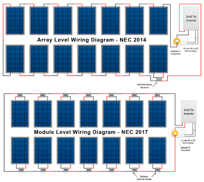
Solar panel wiring diagram. Step by step PV Panel installation tutorials with Batteries UPS Inverter and load calculation. ... SMA rapid shutdown box mounted under solar modules RS SMA rapid shutdown push button disconnect switch mounted outside and. Keep in mind that the number of solar panels and batteries depends on the load requirements ... SMA, Rapid Shutdown Box, 600V, 4 strings, 2 in parallel per channel, RSB-2S-US-10. The SMA Rapid Shutdown System is the most cost-effective way to achieve 2014 NEC 690.12 Rapid Shutdown compliance for systems using Sunny Boy inverters. This DC powered system allows for the use of Secure Power Supply, providing opportunity power to homeowners ...
DOWNLOAD. Wiring Diagram Pictures Detail: Name: fronius rapid shutdown wiring diagram - Sma Inverter Wiring Diagram Refrence Install Sma S Rapid Shutdown System. File Type: JPG. Source: sandaoil.co. Size: 1.83 MB. Dimension: 3900 x 2925. DOWNLOAD. Wiring Diagram Images Detail:
Sma rapid shutdown wiring diagram
Off-Grid capable/SMA Fuel Save Controller compatible / SMA Smart Connected (proactive monitoring and service support) Certifications Certifications and approvals UL 1741, UL 1699B Ed. 1, UL 1998, CSA 22.2 107-1, PV Rapid Shutdown System Equipment FCC compliance FCC Part 15 Class A or the installation of the Rapid Shutdown System is faulty or the Rapid Shutdown Box is defective. The product is certified for use in PV systems with the following SMA inverters: • SB 3000TL-US-22 / SB 3800TL-US-22 / SB 4000TL-US-22 / SB 5000TL-US-22 / SB 6000TL- Jan 20, 2017 · However it should goes to one side of rapid shutdown on/off switch (+12V_ – X2). No. 3 wire from Rapid Shutdown Box which is (o) should go to common wire (jumper wire of both LED’s) of both led (red and green). I am comparing wiring pin diagram on page 23 fig 8 which shows 1-5 connections pins inside rapid shutdown box.
Sma rapid shutdown wiring diagram. SMA, TS4-R-F, Fire Safety Shut Down Module, NEC 2017 SunSpec Compliant Module Level RSD when used with SunSpec Inverters (-41 SMA), Add-on-Module for 1 PV Module, Max 90Voc, 12.5A, 20A Fuse, 478-00252-42. The new TS4-R-F rapid shutdown solution is a cost-effective way to fulfill UL 1741, NEC 2014 and NEC 2017 requirements. 10/09/ SMA Surpasses 1 GW Installed Solar in Latin America. 09/26/ SMA is Now Shipping TS4-R-F Rapid Shutdown Solution for NEC Compliance. More than an inverter — the new Sunny Boy — the next generation of the globally successful Sunny Boy TL. TS4-F/TS4-R-F Installation and Safety Manual. Scott Muir. 2 years ago. Updated. For all Tigo Installation and Safety Manuals, as well as product quick start guides, h ere is a link to the Tigo Guides and Manuals section of our Downloads page. TS4-F RAPID SHUTDOWN SYSTEM 4 • NEC2017690.12Rapidshutdown compliant • Module-leveldeactivation • PLCcommunication • Plug&play,noconfigurationrequired • Rapid Shutdown System Transmitter for rapidshutdownactivationofTS4-F,TS4-R-F, orTS4-A-Funits ... RSS TRANSMITTER WIRING – ...
An electrical diagram will be required when applying for your permit and for final inspection. Sma rapid shutdown box mounted under solar modules rs sma rapid shutdown push button disconnect switch (mounted outside and adjacent to the service panel) #18 awg thwn, 600v rated wire, ½ emt. Source: Assortment of solar panels wiring diagram ... So we tried to uncover some great solar net metering wiring diagram. Interconnecting Customer PCC. Distributed Energy Resource DG. Actually we have been remarked that solar net metering wiring diagram is being one of the most popular issue at this time. SMA rapid shutdown box mounted under solar modules RS SMA rapid shutdown push. Tigo was founded in Silicon Valley in 2007 to accelerate the adoption of solar energy worldwide. Tigo systems operate on 7 continents and produce gigawatt hours of reliable, clean, affordable and safe solar energy daily. Tigo's global team is dedicated to making the best MLPE on earth so more people can enjoy the benefits of solar. The SMA Rapid Shutdown System consists of one or more Rapid Shutdown Boxes (RSB) and one Rapid Shutdown Controller (RSC). The RSB is a tw o channel device. Each channel is capable of operating at 20 Amps of PV current and has a Maximum Circuit Current rating of 36 Amps. In many cases, three or more strings may be connected to each Rapid
A wiring diagram is a type of schematic which makes use of abstract pictorial icons to reveal all the affiliations of elements in a system. SMA rapid shutdown box mounted under solar modules RS SMA rapid shutdown push button disconnect switch mounted outside and adjacent to the service panel 18 AWG THWN 600V rated wire ½ EMT. RAPID-SHUTDOWN-SYSTEM-NEC-690.12. Small Breaker Boxes. Software. Surge Protection Devices. Transfer switches. Wind and Hydro. All DOCUMENTS Accessories Ads Article AutoCad & Visio Drawings Brochures Compliance Certificates ... Wiring Diagrams - SMA / PDF Wiring Diagrams - SMA / Visio or AutoCad Home » Tanpa Label » Cartoon афт Propeller Png - Spinoff Png Images Pngegg - With the adoption of the 2017 NEC electric code, it'll become harder and harder to get your system approved by the inspector without rapid shutdown requireme...
Fronius Rapid Shutdown Wiring Diagram Download. fronius rapid shutdown wiring diagram - Just What's Wiring Diagram? A wiring diagram is a kind of schematic which uses abstract pictorial signs to show all the affiliations of elements in a system. Electrical wiring layouts are made up of two points: signs that represent the parts in the circuit,…
SMA’s SunSpec certified rapid shutdown device offers the fastest, most reliable, and safest method for complying with NEC 2017 690.12. Using far fewer components than more complex alternatives, SMA’s SunSpec certified shutdown device is a plug-and-play solution that operates on a simple powerline signal, reducing commissioning requirements.
wiring if service is required. Wait 30 seconds after rapid shutdown activation before disconnecting DC cables or turning off DC disconnect. • Always assume TS4 units are in "ON" state, or may turn on when restarting. • The CCA must be on the same AC branch circuit as the inverter to meet rapid shutdown requirements.
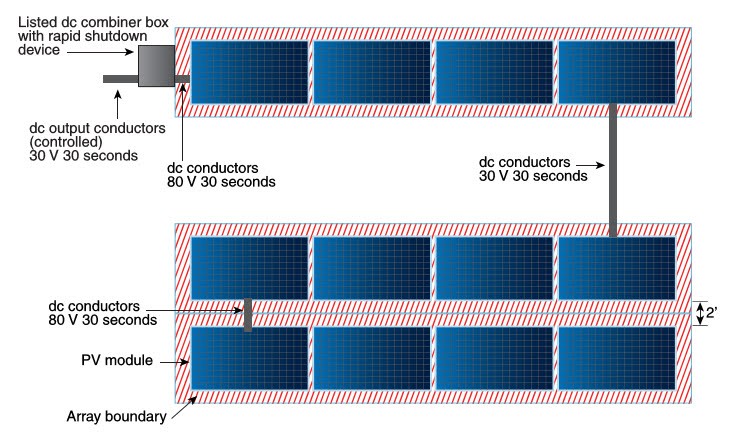
Nec 690 12 Rapid Shutdown Of Pv Systems On Buildings Part 1 Inverters Solar Power News Diy Solar Tips
Note: this wiring diagram is simply an example. Diagrams may vary. SMA rapid shutdown box mounted under solar modules RS SMA rapid shutdown push button disconnect switch (mounted outside and adjacent to the service panel) #18 AWG THWN, 600V rated wire, ½" EMT
The SunSpec Rapid Shutdown System (model JMS-F), available from SMA, is the most cost-effective and reliable solution for fulfilling NEC 2017 module level shutdown requirements. The module-level device is certified for compatibility with the SunSpec communication signal and SMA inverters, making compliance simple and easy.
outfitted with SMA TS4-R-O devices. ... BACKGROUND. The TS4-R-O devices have built-in rapid shutdown functionality in accordance with NEC 2017 Article 690.12. The rapid shutdown functionality is designed to be triggered when the AC power connection ... A simple diagram showing the wiring method for Secure Power Supply functionality with TS4-R-O ...
-----SMA America - https://www.SMA-America.comSMA Inverted Blog - https://www.SMAInverted.comSMA America on Facebook - https://www.facebook.com/SMAAme...
Replacement eaton fuller air shift knob please verify oem number before purchase. This is the actual shift er for 18 speed eaton fuller transmission. Direct aftermarket replacement for oe a 69 18 a 5013 shift the transmission between the top two gears. Buy eaton fuller 4300764 diagram. And above and gcws over 90000lbs.
SMA rapid shutdown box mounted under solar modules RS SMA rapid shutdown push button disconnect switch mounted outside and adjacent to the service panel 18 AWG THWN 600V rated wire. This wiring diagram is simply an example. 32 Wiring Diagram Of Solar Panel System Bookingritzcarlton Info Solar Panels Best Solar Panels Solar Power System How […]
Wiring of the product must be made by qualified personnel only. SMA Solar Technology America LLC Table of Contents User Manual 5 STP50-US-40-BA-en-10 ... SMA Solar Technology America LLC 1 Information on this Document User Manual 7 STP50-US-40-BA-en-10 1 Information on this Document 1.1 Validity
Rapid shutdown time 10 seconds Warranty (contact SMA Service Line) 25 years SunSpec certified SMA inverters Sunny Boy US (SBx.x-1SP-US-41) Sunny Tripower CORE1-US (STP xx-US-41) Type designation JMS-F SMA part number 119814-00.01 Package quantity 40 SYSTEM DIAGRAM SMA America, LLC Toll Free +1 888 4 SMA USA www.SMA-America.com BRACKET DIMENSIONS
Nov 17, 2020 · Sma Rapid Shutdown Wiring Diagram from cdn10.bigcommerce.com. Print the electrical wiring diagram off in addition to use highlighters in order to trace the routine. When you use your finger or even the actual circuit with your eyes, it’s easy to mistrace the circuit. 1 trick that I actually use is to print a similar wiring plan off twice.
Rapid shutdown time 10 seconds Warranty (contact SMA Service Line) 25 years SunSpec certified SMA inverters Sunny Boy US (SBx.x-1SP-US-41) Sunny Tripower CORE1-US (STP xx-US-41) Type designation JMS-F SMA part number 119814-00.01 Package quantity 40 SYSTEM DIAGRAM SMA America, LLC Toll Free +1 888 4 SMA USA www.SMA-America.com BRACKET DIMENSIONS
The rapid shutdown initiation methods shall be labeled in accordance with 690.56(B). Equipment that performs the rapid shutdown shall be listed and identified. NEC 2014 690.12 Rapid Shutdown. But those six short sentences had a big change on PV system design.
Jan 20, 2017 · However it should goes to one side of rapid shutdown on/off switch (+12V_ – X2). No. 3 wire from Rapid Shutdown Box which is (o) should go to common wire (jumper wire of both LED’s) of both led (red and green). I am comparing wiring pin diagram on page 23 fig 8 which shows 1-5 connections pins inside rapid shutdown box.
or the installation of the Rapid Shutdown System is faulty or the Rapid Shutdown Box is defective. The product is certified for use in PV systems with the following SMA inverters: • SB 3000TL-US-22 / SB 3800TL-US-22 / SB 4000TL-US-22 / SB 5000TL-US-22 / SB 6000TL-
Off-Grid capable/SMA Fuel Save Controller compatible / SMA Smart Connected (proactive monitoring and service support) Certifications Certifications and approvals UL 1741, UL 1699B Ed. 1, UL 1998, CSA 22.2 107-1, PV Rapid Shutdown System Equipment FCC compliance FCC Part 15 Class A


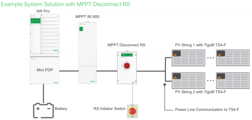


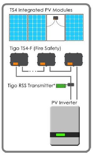


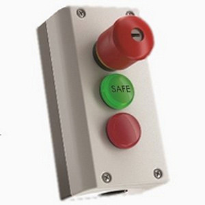




0 Response to "38 sma rapid shutdown wiring diagram"
Post a Comment